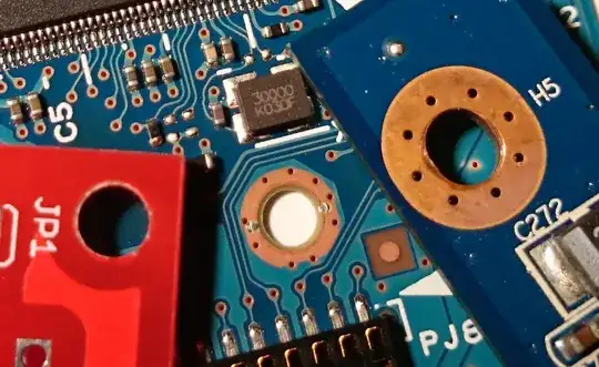
Here is a picture of 3 mounting holes on three different PCBs.
The red one is what I prepared on Eagle CAD and used "hole" button on the left side menu , something like this:
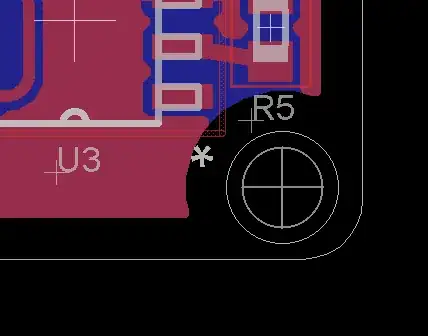
- Do I need to use "via" in order to have the same style mounting hole on the other PCBs?
- As far as I can see, they are vias on the blue PCBs. Isn't it better to isolate the mounting holes on a PCB? What I am thinking to have a risk to get an unwanted signal or voltage to your ground plane as it is unisolated? or Does it improve grounding or tying grounds of unconnected PCBs?
- Is it a gold finish on the mounting holes? Why would I want to have a gold finish on a screw hole that would increase the cost?
- The mounting holes on blue PCBs have several holes on it, what is the purpose of having holes on the screw holes? Fabrication-wise, it seems it would slow down the production a little bit as each individual mounting(or screw) hole requires drill holes on it.
The upper blue PCB is from a projector, the bottom one is from a harddisk of a PC.