1

In this post Design for a Precision LCR Meter the author says:

Current is measured via a transconductance amplifier (again with programmable gain) which produces a voltage proportional to the current through it, but without the ‘burden voltage’ associated with a simple resistor as used in most current measurement.

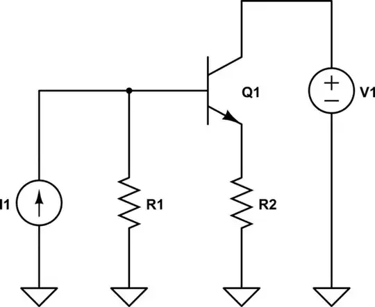
How is this achieved? All the information I have found regarding the use of OTAs shows them using an input voltage to control an output current, rather than the other way around as described above.

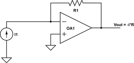
It should be possible to measure current using a current amplifier or integrator as shown below (the integrator circuit would be the same as below except with a cap in place of R1) however both those options still require the use of a burden resistor or capacitor.

schematic

simulate this circuit – Schematic created using CircuitLab

The way the quote is worded suggests the author had a different approach in mind.

  1. Is is possible to measure current using an OTA without the use of a burden component?
  2. Are there any other ways to precisely measure small currents without introducing burden components?
Math Keeps Me Busy
  • 18,947
  • 3
  • 19
  • 65
Sam
  • 65
  • 2
  • 6

3 Answers3

5

This is not so much an answer, since answers have already been given, as an addition that is to long for a comment.

a transconductance amplifier (again with programmable gain) which produces a voltage proportional to the current through it

The author is confused or sloppy. A transconductance amplifier converts a voltage input to a current output:

$$i_{out} = g_mv_{in}$$

As the other answers imply, a transresistance (transimpedance) amplifier converts a current input to a voltage output:

$$v_{out} = r_mi_{in}$$

As you may know, an ideal transresistance amplifier has zero input resistance (and zero output resistance) so the input current does no work on (delivers no power to) the input. I suppose this is what is meant by 'burden'.

The ideal (ideal op-amp etc.) circuit George Herold gives has zero input resistance and zero output resistance.

Alfred Centauri
  • 26,502
  • 1
  • 25
  • 63
3

The opamp version of a TIA looks like this, (one of my fav. circuits.)

schematic

simulate this circuit – Schematic created using CircuitLab

George Herold
  • 4,754
  • 1
  • 18
  • 25
  • 1
    A transimpedance amp does not equal a transconductance amp. – Matt Young Nov 05 '14 at 23:03
  • @MattYoung, Ahh, OK fine. I was trying to answer the question of how to turn current into voltage. (How would you do this with an OTA?) – George Herold Nov 05 '14 at 23:30
  • @MattYoung, what is the distinction? In my organization we use the terms interchangeably, but that may be sloppiness. – The Photon Nov 05 '14 at 23:56
  • @ThePhoton The distinction I was taught is the transimpedance amplifer is a CCVS, and a transconductance amplifier is a VCCS. – Matt Young Nov 06 '14 at 01:05
  • @GeorgeHerold I never really thought about it, but a OTA would be a great way to amplify a sense resistor's voltage. They are very close to linear as long as the input voltages are kept small (I was taught <20mV). If you sized a sense resistor to drop 20mV at full scale, and sized the set and output resistors accordingly, the output voltage would fill the span of an ADC easily. I can't think of a way to do it without a sense resistor. As Alfred Centauri pointed out already, the author is describing a TIA. – Matt Young Nov 06 '14 at 01:13
  • @MattYoung, you're right, sorry to bug you. I was thinking of transimpedance and trans-resistance amps. – The Photon Nov 06 '14 at 01:46
2

A transimpedance amplifier like George drew. A transconductance amplifier could be used, but usually they're pretty sloppy compared to a good op-amp in that configuration.

Another way would be to use a balancing Hall effect circuit- an amplifier produces a current, causing a magnetic field to cancel the field caused by the conductor in which you're measuring current.

All three methods can have arbitrarily small burden depending on how good your amplifier is. The first two require your circuitry to supply the entire current being measured, with the latter you can scale it by the ratio of turns in the measuring coil vs. the balancing coil (in other words, if you're trying to measure 100A with 1 turn, you could balance the field with 2000 turns and 50mA from the amplifier.

Spehro Pefhany
  • 376,485
  • 21
  • 320
  • 842