17

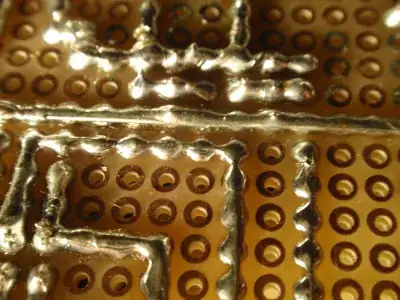
I have a PCB which has the perfect size for a project of mine, so I would like to use it if possible. However, the copper plating on the back side of PCB only surrounds the individual holes (that is, no holes are interconnected). See picture right here:

Strange PCB

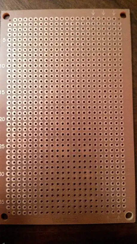
I find this strange. How can this be useful? I would definitely need some copper tracks with interconnected holes in there because some components need to be connected to each other. Am I supposed to make my own tracks somehow?

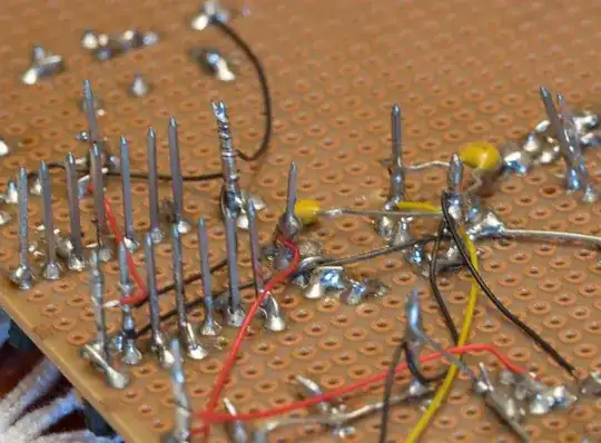
I saw some stuff online about people who would insert multiple wires in the same hole to make interconnections, but this seems undesirable. I'd rather avoid that if there is some way to make tracks.

Peter Mortensen
  • 1,676
  • 3
  • 17
  • 23
Martin Horton
  • 181
  • 1
  • 6
  • possible duplicate of [How to make traces on an universal PCB?](http://electronics.stackexchange.com/questions/55236/how-to-make-traces-on-an-universal-pcb) – Ignacio Vazquez-Abrams Nov 01 '14 at 02:40
  • That's a prototype board. You solder devices (usually with sockets) to it, then run wires from pin to pin. – Hot Licks Nov 01 '14 at 20:40

6 Answers6

25

What you've got is called a prototype board. It is available at electronics suppliers everywhere and is obviously not meant for production. Join things together any way that is convenient for you. Many methods have been pictured. Another common way is inserting a component lead beside its next connection and just bending it over to fit.

The results are typically quite messy, but it can take a lot more handling than a breadboard prototype. Thus it is a common step before getting printed and etched boards made.

You can also find prototype boards in the same circuit pattern as the push-in breadboards, so you can simply transfer your circuit from one to the other, solder, and install.

Peter Mortensen
  • 1,676
  • 3
  • 17
  • 23
paul
  • 2,083
  • 14
  • 7
  • I picked this answer mainly because it went over the terminology (I didn't know that this was called a Prototype Board) and where these boards fit into the development cycle. Otherwise, I think everyone gave a good answer and I wish I had enough reputation to upvote them all but sadly I can't right now. Thank you everyone! – Martin Horton Nov 01 '14 at 03:17
  • 1
    Is "prototype board" a common naming convention? You link to the wikipedia page for perfboard, which is the name I've heard used more often – Ryan Nov 03 '14 at 00:01
  • 1
    This board is also very useful for one shot production. As I pretty much never make the same device twice, I use these a lot. – Pentium100 Nov 03 '14 at 14:38
  • @ryan I would have regarded "prototype board" as a more general term covering this type of board but also covering other types like stripboard, tripad board, boards laid out like breadboards and so-on. – Peter Green Mar 12 '16 at 02:56
19

The holes on a board like this are close enough and large enough that one can make solder bridges in order to wire components together. It takes a bit of practice but can be decently reliable.

Ignacio Vazquez-Abrams
  • 48,282
  • 4
  • 73
  • 102
  • But is it a preferred method? I mean not aesthetically. Whats the better way of soldering on perfboards? – ammar.cma Sep 29 '16 at 08:18
  • The preferred method is to talk to a low-run PCB manufacturer and get proper boards done for $cheap per unit. If you choose to go the DIY way then you do what you need to. – Ignacio Vazquez-Abrams Sep 29 '16 at 08:22
18

One technique is to use wires (or extra leads from resistors/LEDs etc.) to create the "interconnected holes" you speak of.

enter image description here

NickHalden
  • 4,167
  • 3
  • 31
  • 40
18

In addition to using component leads and tinned copper wire to form connections between components sometimes I find insulated wire-wrap wire useful. In the following example I've used a proper wrap tool and wire-wrap posts but it can also just be stripped and soldered. Another good style of wire to use is the insulated solid core wire like you find in some styles of telephone cable.

enter image description here

PeterJ
  • 17,131
  • 37
  • 56
  • 91
9

Boards like this are typically used with jumper wires (the "multiple wires in the same hole" method you mentioned). An alternative way to make tracks would be to use a circuit conductive pen as demonstrated in this video.

I personally like to use wire-wrap wire since it is thin and easy to insert several per hole. Once you get used to using it, it can be very quick and efficient.

ken
  • 411
  • 3
  • 7
2

It's possible to solder a component to the rings, and then use wires or solder bridges to interconnect such components (in many cases I find wires easier). The presence of the rings will make things mechanically quite stable, so even uninsulated wires may be used in many cases without shorting. In the absence of the solder rings, one might bend component legs in an effort to hold components in place, but such fastening would seldom be rigid. When components are soldered together, the bent pins would keep them from moving very far out of position even if there were no interconnecting wires, but it would be the interconnecting wires themselves that actually held the components in position. Such connections would thus be prone to much more mechanical stress than would be the case if components were soldered to the board, and would thus as a consequence be much more prone to failure.

supercat
  • 45,939
  • 2
  • 84
  • 143