19

Sometimes you need to ensure that your oscilloscope probe ground lead is not creating measurement error such as ringing and overshoot. In various forms, I have seen (and successfully used) a ground spring for measuring a circuit. I have shamelessly borrowed AndrejaKo's image to make sure we're all on the same page:

Oscilloscope probe with spring-type ground connector

I have determined that this lead length is essential in some of my test configurations, but it requires constant attention to make sure I'm not shorting something out, loosing a connection, or probing the wrong thing. This limits my ability to do other tasks in the test setup, and makes it impractical for other setups that do not allow that sort of access safely (blind or hazardous conditions).

How do I attach a scope probe to the circuit under test with a 1/2" (1cm) ground lead, or otherwise get a hands-free high bandwidth setup?

W5VO
  • 18,303
  • 7
  • 63
  • 94
  • 1
    I've been known to solder hooks made from resistor legs, or in extreme cases SMA sockets, to prototype PCBs... –  Oct 27 '14 at 23:48
  • @BrianDrummond But that isn't exactly going to stay in place, is it? What about SMT parts? Loose, exposed wire leads to exciting fireworks. – W5VO Oct 28 '14 at 04:36
  • 1
    One warning about using an SMA socket as a scope probe tip jack: after several insert/remove cycles with no mechanical strain relief, the SMA contact leaf can become deformed, making intermittent contact. – MarkU Oct 28 '14 at 05:45

4 Answers4

22

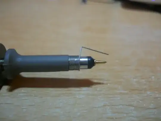
The kind of tip you show is not intended for permanent installation.

If you need to have a scope hooked up to the device under test, with good high frequency performance, the only good solution is to design testing connections into your device.

I like MMCX connectors, because they're very compact, and you can get MMCX->SMA pigtails (and convert that to BNC) for cheap.

enter image description here

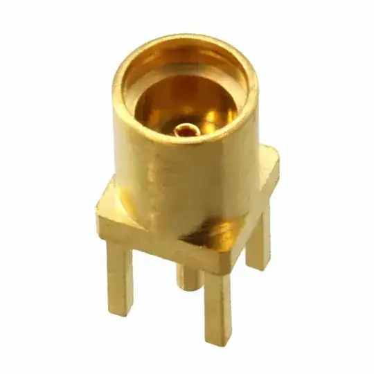
You do have to design testing into your project, but it's a good habit to get into anyways. I tend to try to scatter MMCX footprints around my board layouts, so I can get easy probe access to any nets I'm interested in. Plus, they make decent pads for probing with a spring ground clip if you don't want to solder connectors down.

You can also make a homemade alternative, if you have the board-space and patience:

enter image description here

As W5VO points out in the comments, using a test-setup like this for high-speed connections can be somewhat challenging. You would need to either construct a 10:1 probe adapter with a compensation capacitor, and mount it right on the mating MMCX connector, or properly ensure that your connecting cable is 50Ω, and the oscilloscope you're using is set to 50Ω input impedance to prevent reflections and signal distortions.

If you are interested in high-speed logic probing, a simpler solution then dealing with having to terminate the signal run to your scope would be to use a homemade inline termination as close to the MMCX connector as possible.

Basically, you can homebrew a 10:1 or 20:1 probe by simply inserting a series termination as close to the connector (the PCB-end connector) as possible. With a 50Ω scope imput impedance, a series resistance of 450Ω results in 10:1 attenuation, while maintaining proper impedance matching to the oscilloscope, and also loading the circuit under test much less.

A 950Ω resistor would result in 20:1 attenuation.

There are several homemade probes using this technique here and here.

For this sort of setup, I would take a male and female PC-mount connector, and solder the resistor in between the two, with some bare wire connecting the ground pins. It should be quite compact and structurally robust.

You can even add a compensation capacitors if you're interested in very high speed signals. There is a good resource about that here.

You then simply insert the series termination inbetween the scope lead and your board under test, and set your scope to the proper attenuation.

Connor Wolf
  • 31,938
  • 6
  • 77
  • 137
  • 1
    To sorta flesh the RF connector thought out, you would be running the scope as a 50Ω input, and use a resistor-divider technique to get the amplitude to an acceptable impedance and voltage range? – W5VO Oct 31 '14 at 13:43
  • 1
    @W5VO - That depends on whether you're trying for low noise or controlled impedance connections, but for the latter, yes. – Connor Wolf Nov 01 '14 at 06:07
  • 3
    My concerns are with fast rising and falling edges, and my voltages are high enough that I can't use 50Ω mode directly. I'd imagine you'd get a bunch of nasty transmission line effects if you just used 50Ω coax straight to the 1MΩ input of the scope. I'm trying to minimize ground loop for high-speed signals. – W5VO Nov 01 '14 at 08:13
  • 1
    @W5VO - That is a completely valid point. I'll admit that I primarily use embedded connectors like the one I show to get a very robust, low noise connection so I can do high precision analog verification, all at frequencies well below 1 MHz, so I have not really considered the high frequency requirements. You make excellent points. – Connor Wolf Nov 01 '14 at 08:44
  • 1
    Basically, another advantage of this sort of test-setup is that, provided your device-under-test is not grounded to earth, you get a very good quality local ground connection (and no ground loops) with a RF connector. When you're looking at < 1 mV signals, having just the ground clip lead running to a ground connection a inch or two away can swamp your signal of interest with ground differences. – Connor Wolf Nov 01 '14 at 08:46
  • @W5VO - Added some more thoughts on how to use a setup like this for high-speed probing. Opinions? – Connor Wolf Nov 01 '14 at 09:02
  • Yes, I was completely focused on how to attach the scope probe that I forgot about the resistor-divider probe method. That should work with my current setup, but it will have issues at higher voltages (300VDC+) where I really need the high impedance of a passive probe. – W5VO Nov 02 '14 at 02:25
  • @W5VO - This is a passive probe! For high voltages like that, you can increase the divider ratio. A 100:1 probe would probably be completely useable, and only have ~10KΩ loading. You could probably even get away with 1000:1. You could also probably chop up a traditional passive probe and stick a SMA or MMCX connector on the tip if needed, and that would get you the traditional 10MΩ. – Connor Wolf Nov 02 '14 at 07:56
  • I'm less worried about loading on the signal and more about power dissipation in the dropping resistor. At 300V, 10k gives you about 9W of power. – W5VO Nov 02 '14 at 13:06
  • @W5VO - That..... is a very good point. Hmmmm. In that case, building or repurposing a traditional 10:1 probe sounds like a better idea. The challenge there is you need some little tiny variable capacitors for the compensation capacitors. – Connor Wolf Nov 02 '14 at 13:59
  • Basically, traditional 10:1 probes use specialty coax cable, and I have no idea where to buy that short of just chopping up a probe. – Connor Wolf Nov 06 '14 at 19:58
8

One trick is to create tiny "craters" in the cold solder of the test points with some sharp tool. This might sound destructive at first, but IMHO it is far less destructive and takes less effort than soldering some wires. Sharp scope probe tips are also to prefer before blunt ones. Place the scope probe tips in these craters when you are measuring. Even the craters might look small they are often sufficient to prevent the probe tips from sliding off the test points.

Another method I learned from Lecroy is applicable for measuring on IC:s. The idea is basically to duplicate the ground plane on top of the IC with a small copper pad. See page 65 in the following Digikey/Lecroy presentation

boink
  • 319
  • 1
  • 7
2

First, wind the bare buss wire around the probe (as you see in the photo); it will be loose and not quite stay on. The trick is you next take it off, and give it a gentle little squeeze (deforming it maybe about 0.1mm smaller), so that it is slightly smaller than the diameter of the probe. This ensures that it will fit snugly when you insert the probe.

If you want a more reliable way to generate these "ad hoc" scope probe ground jacks, check your local hardware store for some wooden dowel stock in the nearest size smaller than the probe body. Then, when you wind the wire around the dowel stock, the resulting "spring" will be smaller than the probe body. If it's too small, you can gradually increase its thickness by winding electrical tape around the dowel stock until it is the right size.

MarkU
  • 14,413
  • 1
  • 34
  • 53
  • 1
    I think the OP is tring to find the mest method to get a reliable connection form the spring to the device under test - not between the spring and the probe. – RJR Oct 28 '14 at 06:11
  • 1
    As RJR suspects, I don't have any issue *making* or *using* the traditional spring ground clip, my problem is that it doesn't stay connected to the circuit if I remove my hand. – W5VO Oct 28 '14 at 06:17
  • 2
    Solder it in place? – MarkU Oct 28 '14 at 06:24
  • You would solder the tip of a $500 scope probe to your board? – W5VO Oct 28 '14 at 06:38
  • 2
    No no, don't solder the actual scope probe -- I mean just solder the buss wire "spring". You can make one coil to fit the ground sleeve of the probe, and a smaller coil to fit the probe tip. – MarkU Oct 28 '14 at 07:36
  • 2
    Once you solder the spring you can wind some 30 gauge bare wire around the tip making a small socket for the tip. Twist the two ends of the wire while it's still around the tip to form a tail, (and to make it tight) solder the tail to the test node, solder the ground spring you made above to a ground the right distance away and you can have a semi-permanent scope probe socket on your board. – John D Oct 28 '14 at 16:03
  • @W5VO - You can have one probe that you solder in place as necessary (and reuse). Also- the tips of some probes are replaceable, so it's not like you are wasting a $500 scope probe if you ever need it to work like it used to. – plasmo Oct 25 '20 at 21:55
1

Tektronix makes a circuit board clip, part number 131-5031-00. It is a bit hard to find information about it, but Newark has a high resolution image.

plasmo
  • 148
  • 3
  • In the past, my issue has always been with getting a hold of 1-2 of those at a time. I also believe that you need to find the correct socket for your probe, as some of the high-voltage probes use different dimensions. – W5VO Oct 26 '20 at 15:22