14

I want to connect a sound board / mixing console / whatever-you-prefer-to-call-it to the headset jack of my Motorola Android phone. I know the typical TRRS pinout of Left/Right/Ground/Microphone, and I know about the mic being phantom-powered by the phone and using the external impedance to detect:

  • speakers only (long-duration short, could be fooled by direct connection to a line-out)
  • play/pause button (short duration short)
  • prev/next buttons (2 different impedances < 1kohms)
  • microphone present (impedance > 1kohms)
  • unplugged (open)

So I know I need an attenuator (probably a pot) followed by an RC highpass with R ~2k before it goes into the headset jack. Not a problem. What I can't figure out is, what's this on an unconnected mic?: enter image description here 
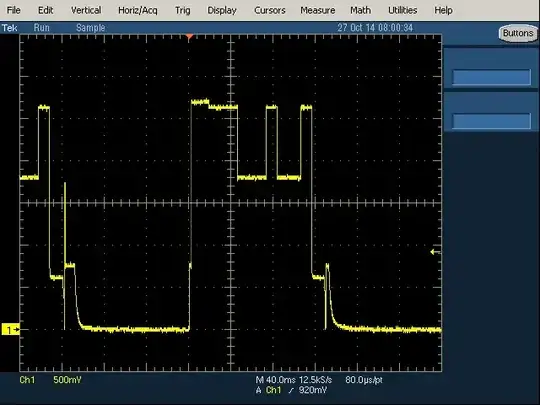
Kinda looks like a digital byte, doesn't it? It repeats the same thing at this rate forever. With a "bit" width of ~10ms (100bps, 50Hz) and a cycle time of ~250ms (4Hz), it sounds terrible. Probably not intended to be heard directly. enter image description here 
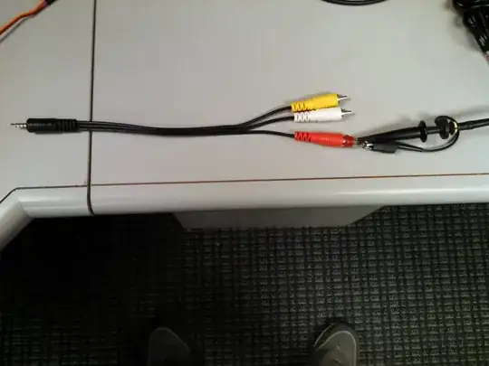
This adapter is intended for cameras, so the color code is wrong. A continuity checker says that the red plug is [S]leeve, which is mic for me.

Update:

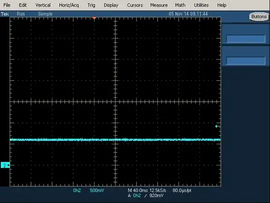
I finally got around to adding a 2.2k termination to the mic plug and now it does this: enter image description here

(same scale as before, just a different color)

I start an app that uses audio in, like an oscilloscope, spectrum analyzer, SPL meter, or call my voicemail, and it changes to this: enter image description here

I don't have a good way to put a signal into it right now, but it looks like it works. I'll just need to add a series resistor to make it play nice with whatever it's plugged into when there's no app running to use it. I'll probably put it between the mixer's line out and the pot so as to guarantee a certain amount of attenuation. (it's still a mic in, not a line in)

The weird thing though, is when I remove the 2.2k termination, I get this instead of the original: enter image description here

Almost like it saw the resistor, configured itself to use a mic now, and didn't go back. I'm still curious to know what it was doing before, but it looks like my project will work.

AaronD
  • 5,596
  • 10
  • 36
  • You're probably looking at a class D headphone output. –  Oct 27 '14 at 18:22
  • 1
    While this might be technically correct (I can't personally say either way), one sentence answers aren't really helpful. Can you add anything else to this in support/explanation? – Adam Head Oct 27 '14 at 18:28
  • No, a continuity checker says that that plug goes to the [S]leeve, which is the mic input. The other two are [T]ip and [R]ing, for left and right output, and they behave accordingly when I plug them into the sound board's inputs. The common ground connects to the other [R]ing, as expected. – AaronD Oct 27 '14 at 19:01
  • 4
    Besides the pinout not making sense for an audio out, the waveform is wrong too. A lousy class D amp would be an unfiltered or barely filtered square wave. Much simpler than what I have. A good class D amp would be a flat line unless I zoom in a lot, in which case it would start to look like the bad class D amp if it weren't buried in the noise. If you look at the scales, I think it's pretty clear that this isn't intended to be heard directly. – AaronD Oct 27 '14 at 23:20
  • Really interesting question. The only thing I can think to ask is how much do you trust your testbench? Those first two signals look like something that could happen due to mains voltage on a shoddy o-scope. – Michael Leonard Nov 05 '14 at 23:55
  • @Michael How do you see that? I've seen spikes at AC peaks before, probably from diode rectifiers, but the blue one is the wrong frequency for the 60Hz power here, and the yellow one doesn't look like anything that might come from the mains as far as I know. The other two are nice flat lines like I expected to start with. I got the yellow one on an analog 'scope before I captured it to post here. Looks exactly the same except for the low-level noise. – AaronD Nov 06 '14 at 00:30
  • 1
    Should probably clarify, I wasn' implying that the signal is from direct injection of mains voltage but that the very regular nature of the signal and the low frequency would suggest that the effect is being caused by the regular/low frequency variation on mains. Perhaps from faulty internal components or something like that. I'm certainly not convinced that is the case or I would have posted as an answer, just seems like something worth considering. – Michael Leonard Nov 06 '14 at 01:11
  • @Michael Maybe, at least for the blue one. But I think it's much more likely to be an artifact of periodic sampling that just happens to run at 20Hz or so. I'm more interested in what the yellow one is. I think it'd be really hard to get that out of an AC power line. Maybe it's a debug / diagnostic connection code? Reboot the phone and it tries to connect to a debugger until it sees a mic? I'm an embedded software engineer, so I'm just speculating based on what I know. – AaronD Nov 06 '14 at 01:32

2 Answers2

1

From diagram 3, I could think of two possibilities:

  1. The microphone interface is polling for an existence of a mic periodically and turning the line off when not found. Probably not correct.

  2. The mic input is doubled as another digital interface. Some phones have a way to detect whether the plugged in ear phones are manufacturer's original models or not, for example. If such a earphone pair is detected, the internal audio equalization may be tweaked to produce best possible fidelity.

The pulse shows narrow, I could not sit and figure out it's width, but it does look like a start bit for me. Assuming it is a start bit, it is probably followed by, say some bits and a stop bit - all are zeroes (like a UART). Beyond that, the controller probably is expecting a response.

The first diagram probably is the mic decoupling capacitor acting as weird RC filter with oscilloscope input impedance. Open drain outputs usually require a remote termination. That's another way to detect if remote is connected, somewhat like USB.

Which is the phone on the other end? I might not have access to the same model and I definitely don't have a similar cable handy to figure exactly out what is happening.

It might be interesting, though, to try sending an UART response on the line, taking the high pulse width as bit time: wait for ten or 11 bits and send high start bit and probably try some combinations. Even if we get a response, it might take a while to figure out the protocols etc. I would advise extreme caution, though - if it is a dangerous interface like a firmware backdoor, a trial sequence could potentially erase the flash.

Vasu
  • 129
  • 5
  • If it's a digital interface, which I think it probably is, then I think the first one (yellow) is the one to look at, not the third (blue like the rest). To me, it looks and awful lot like enabling a DC-offset comms driver, transmitting a byte, and disabling again. I think it'd be really hard to make an RC filter do all of that even if you tried. – AaronD Jan 07 '15 at 17:48
  • Your point #1 is probably correct for the blue pulses, and your point #2 might be correct for the yellow ones. But if that's true, then the question is, "Why doesn't it restart the digital out in case it finds a compatible set?" – AaronD Jan 07 '15 at 17:51
  • @AaronD: Did you plug in a compatible set? Maybe, the driver logic or other software logic would not poll a change on the socket line all the time. Even more important, I guess, is the compatible headset should be digital capable for the interface to switch to digital mode. Otherwise, we might be missing the one shot "Go Digital" attempt and are seeing only the analog line as in figure 4 or 5. I've seen code with such behavior: init loop different from main control loop. I'm still guessing, could be more accurate if I got to see the board and/or cable with an Oscilloscope. – Vasu Feb 02 '15 at 11:13
  • By "compatible set", I meant ~2kohms as per the standard. Yes, I gave it 2kohms, and it did as expected as per the standard. Please read the entire report. – AaronD Feb 02 '15 at 14:09
  • This thing that seems non-standard is only at the start of the test procedure, if you will, where the first step is to observe what's already there. If you were to gleefully plug in a standard analog headset, you might never know this. – AaronD Feb 02 '15 at 14:09
  • That said, you could be correct about it looking for a digital set. Thinking about how I might design one and tell it apart from the more common analog standard, this might be a good way to do it: the "ping" attempt is clearly not intended to be analog audio, and to further differentiate it, the signal is entirely above ground by a good margin where audio would not be. – AaronD Feb 02 '15 at 14:20
0

Android allows you to do a ton of crazy stuff on the "headphone" connector. My guess is that something running on your phone is trying to connect to a device that might be plugged in- do you have Square or some other similar app running?

Check out this relevant article: http://www.tested.com/tech/android/522-androids-headphone-jack-is-versatile-yet-underused/

Tom Brendlinger
  • 395
  • 1
  • 8
  • Video? Out of a headset jack? Wow, that sounds like some dedicated hardware that hardly ever gets used. (high-spec DAC at minimum) I'm surprised that a manufacturer would do it without an advertised purpose. I don't have Square or anything else that I would expect to use the headset for comms, but that doesn't mean there isn't one. – AaronD Dec 09 '14 at 15:47