 !
!
Where will the current flow through?
If ON current(back emf "current") will loop through A B and C
If OFF current will(back emf "current") loop through x y and z
!
Where will the current flow through?
If ON current(back emf "current") will loop through A B and C
If OFF current will(back emf "current") loop through x y and z
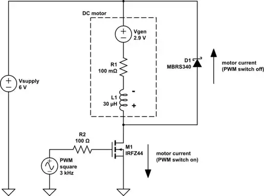
Where you may be confused is that there are actually two back-emfs - the voltage generated by the motor when it is spinning, and the voltage caused by inductance when the PWM switch opens.
A DC motor can be thought of as consisting of a DC generator whose voltage is proportional to rpm, a resistor which represents the resistance of the windings and brushes, and an inductor which represents the armature inductance.
Consider the equivalent circuit below. When the motor is spinning it generates a DC voltage in opposition to the supply voltage. The difference between the supply voltage and generated voltage is impressed across the motor's internal resistance, which determines how much current it draws. As the motor speeds up the voltage difference gets less so current draw reduces, until it is receiving just enough current to maintain a constant rpm. If 50% PWM is applied then the motor 'sees' 50% of the supply voltage on average, so it drops to half speed and the generated voltage is nearly half the supply voltage (slightly less due to voltage lost in the resistor).
During PWM ON time the motor receives full supply voltage, so you might expect the instantaneous current to rise dramatically. However this doesn't happen immediately because the inductance apposes any current increase, generating a back-emf voltage which adds to the generator voltage (polarity is + at the top of the inductor and - at the bottom).
During PWM OFF time the switch is open, so motor current cannot get back to the supply. However once again the inductor opposes current change, this time generating a back-emf voltage in the opposite direction (with polarity as shown by the + and - symbols in the diagram) with sufficient amplitude to maintain current flow. At this point the flyback diode becomes forward biased and motor current flows through it.
The intention is to maintain a constant current through the motor even though it is being continuously switched on and off. In practice the inductor can only slow down current change, not completely eliminate it. However if the PWM frequency is high enough then the current ripple will become a triangle wave of low amplitude.
simulate this circuit – Schematic created using CircuitLab