I found the following examples of POE termination from around the internet:
After posting the same question on TI's E2E forum, I got the following answer:
The majority of termination schemes will follow the examples you've cited and not the SLVU126 (TPS2384) and SLUU269 (TPS23841) TI EVM designs. These EVM designs will tend to have more reference evaluation circuits than any final product design would have. So, in this case a single high voltage ESD capacitor for each port.
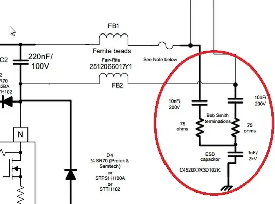
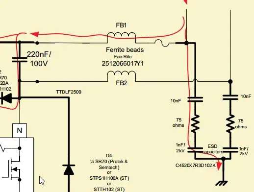
The 10nF capacitors act as a DC block for the PoE port voltage and appear as a short at high frequencies. These capacitors are required on the ethernet pairs which carry the DC voltage but could be removed for the other pair (at least on the PSE end). On the PD end, the 10nF capacitors are required on each pair because the PD can receive DC voltage from either pair set. The 10nF capacitors can be lower cost, voltage and size.
Other good references are located within vendor datasheets who make magnetic's modules such as the Pulse PN JK0-0177NL which is used on http://www.ti.com/lit/pdf/sluuay8. In this case, a single HV ESD cap and 4x 22nF LV caps are used.
So, the second ESD 1nF capacitor is superfluous and I think diminishes the effects of the Bob Smith termination.