8

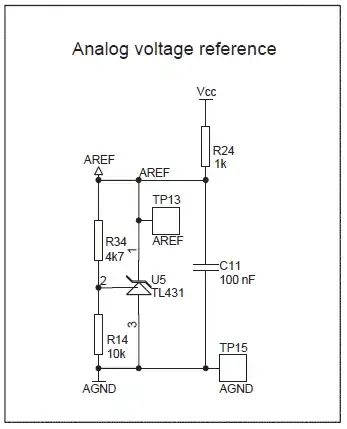
I'm studying the analog voltage reference circuit described in the AVR450 Application Note - Battery Charger for SLA, NiCd, NiMH and Li-Ion Batteries, which schematic is below (copied from page 38).

Analog voltage reference schematic

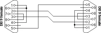
On page 40, there's a schematic showing the MCU connections for the charger where the analog reference circuit is used (picture below). Marked in red there's a component (a BLM-21) whose symbol looks like an inductor, but I'm not sure what exactly it is.

Ferrite bead inductor

I found online that it seems to be a ferrite bead inductor.

My questions are:

  1. What is the purpose of that component in the aforementioned circuit? It looks to me that it may be part of a LC filter with C9. Is that it?

  2. What happens if I omit it?

Ricardo
  • 6,134
  • 19
  • 52
  • 85
  • 4
    Decoupling and EMC. – Ignacio Vazquez-Abrams Oct 15 '14 at 02:11
  • 1
    You did notice the ferrite is connected to `AVCC` and not to `AREF`, right? – The Photon Oct 15 '14 at 04:36
  • @ThePhoton yes I did notice that. Did I say or imply otherwise? – Ricardo Oct 15 '14 at 10:57
  • 1
    Your title asks about a ferrite in a "reference circuit". – The Photon Oct 15 '14 at 14:59
  • @ThePhoton - Oh, yeah, right. It's that I loosely put `AGND`, `AVCC` and `AREF` all in the same bag, so to speak :D Thanks for the reminder, though. I did feel like mixing the bead with `AREF` at least once, by mistake. – Ricardo Oct 15 '14 at 15:04
  • 2
    A related "aside": The app note looks good at a brief glance , but DO verify the algorithms and decisions independently if using it. eg they suggest an SLA can be safely floated at 2.2V/cell indefinitely = 13.2V for a 12V battery. This is 0.5V lower than "currently received truth" suggests and the "small" difference can make a vast difference to battery life. – Russell McMahon Oct 22 '14 at 00:24
  • That's a very good point, indeed, @Russell. Thanks for glancing at the app note. As a matter of fact, I have already detected a few discrepancies that I wanted to get past folks here, regarding NiMH charge rates in the app note. I'll post a question about it when I'm ready. But I'll check the algorithms and termination conditions carefully anyway. – Ricardo Oct 22 '14 at 00:27

2 Answers2

8

Yes, it's basically part of a low pass L-C (or R-C for high frequencies) filter for the analog Vdd on the chip (with C9). Ferrite beads act like very low resistance (< 1 Ohm) for DC, inductors (several uH) for low RF frequencies and they act like resistors (hundreds of ohms to 1K or more) for frequencies in the 100MHz range.

Ferrite beads are normally specified in ohms in the resistive region (relatively high frequency- usually 100MHz) where they are very lossy, but they have an inductive region at lower frequencies. Note that care must be taken with this kind of circuit that noise inherent in the supply does not resonate at high Q with the ferrite and capacitor or the bead may actually result in more noise on the power rail. A good reference on beads can be found here. This sort of thing can cause all kinds of grief if the SMPS noise is (or has a harmonic) close to resonance and it changes with loading or input voltage or temperature to move in and out of resonance.

http://www.digikey.ca/Web%20Export/Supplier%20Content/TDK_445/PDF/TDK_InCompliance_Aug2010.pdf?redirected=1

If you simply omit it the chip will not work properly since there will be no power supplied to Avcc. If you replace it with a short, the chip will operate normally, however you may see somewhat higher noise on ADC readings and possibly other subtle effects on analog performance.

R33 may have been a thought to allow for a ferrite bead in the analog ground (usually not a good idea) or it may be used as a net tie to enforce a single point connection between the analog ground nets and the ground.

Spehro Pefhany
  • 376,485
  • 21
  • 320
  • 842
7

Ferrite beads act as high-frequency noise filter. The beads are manufactured such that certain ranges of frequencies (typically very high frequencies) will excite current flow within the bead and ultimately dissipate as heat, effectively stealing energy away from the noise at those frequencies. Ferrite cores are what you see on most of the cables connected to your computer and TV. They are hollow cylinders that wrap around the outside of the cable to suppress noise.

enter image description here

The ferrite bead on your circuit is contained within a chip and put in series with the line, acting more like an inductor. But manufacturers do not typically give an equivalent inductance value in Henries. Instead, they provide a chart that shows the equivalent impedance of the bead at various frequencies.

For example, ferrite beads from the BLM-21 series in your circuit have an impedance vs frequency graph that looks like this:

enter image description here

You might choose one of these beads if you expect to experience EMI between 20MHz and 1GHz.

The author of that circuit clearly wanted to minimize noise on the analog circuitry of the MCU. Removing the ferrite bead (and shorting AVCC to VCC) may or may not cause inaccuracies in the analog peripherals, depending on whether noise in those frequencies are prevalent.

Dan Laks
  • 8,504
  • 4
  • 27
  • 43
  • +1 Excellent answer, thanks! I was wondering what all those graphs on the datasheets were really for. – Ricardo Oct 15 '14 at 02:28
  • 1
    As Spehro points out, if you remove the ferrite bead you would need to replace with a short/jumper/zero ohm resistor or other very low ohm resistor, otherwise AVCC would be open circuit – KyranF Oct 15 '14 at 08:42
  • 1
    @KyranF, of course. I'll edit my answer to state that explicitly rather than let it be assumed. – Dan Laks Oct 15 '14 at 08:48
  • it might be okay now that the OP has asked a specific question about that on this site, and there were some detailed answers. But for historical reasons perhaps it's a good idea – KyranF Oct 15 '14 at 09:00