1

I know I can use a driver chip to simplify this a lot, but I just want to make sure that I have the concept of H-Bridges down.

Here they are: enter image description here

I have two motors, and each have 4 N-MOSFETs (https://www.sparkfun.com/products/10213). These N-MOSFETs will turn on with just 5v from the Arduino. I have added diodes for when the supply is cut off and the motor produces a voltage.

To move Motor 1 in one direction, I would write HIGH for Digital Pin 1 (D1) and Digital Pin 3 (D3), and so on.

Any feedback would be appreciated.

Michael
  • 31
  • 5
  • The MOSFETs already have diodes going that way. Did you mean for them to be Zener diodes, or even a TVS directly across the motor? – Ignacio Vazquez-Abrams Oct 14 '14 at 17:23
  • 3
    @Ignacio [MOSFET body diode](http://en.wikipedia.org/wiki/Power_MOSFET#Body_diode) may or may not have sufficient rating. They also may or may not be fast enough. So, a faster and beefier external Schottky diode may still be called for. – Nick Alexeev Oct 14 '14 at 17:35
  • 1
    True, but [this one](http://dlnmh9ip6v2uc.cloudfront.net/datasheets/Components/General/FQP30N06L.pdf)'s pretty beefy, and decently fast. – Ignacio Vazquez-Abrams Oct 14 '14 at 17:37
  • 2
    @Michael, Just as a matter of style, it's nicer to show all ground symbols as "pointing down". Showing your battery symbol and the ground upside-down like that makes me start to tip my head sideways to read the circuit. – Dan Laks Oct 14 '14 at 17:45
  • @DanLaks, I wanted the circuit to be symmetrical instead of having a line around the circuit connecting the ground to the battery :( – Michael Oct 14 '14 at 17:52
  • 1
    No need to send the ground line all the way around the circuit. You could just put a couple of bends in the wire around the battery and ground symbol to make everything "upright" right there at the top. Check out Olin's excellent answer (specifically part 3) about schematic layout: http://electronics.stackexchange.com/questions/28251/rules-and-guidelines-for-drawing-good-schematics – Dan Laks Oct 14 '14 at 17:57
  • Ah, okay. Thank for the link! I'll definitely be using it for future reference. – Michael Oct 14 '14 at 18:19
  • Separating the power supply from the rest of it would also help. – Ignacio Vazquez-Abrams Oct 14 '14 at 18:22

1 Answers1

9

"These N-MOSFETs will turn on with just 5v from the Arduino."

Are you sure? Do you expect them to conduct 60A with an Fds of 0.05 Ohm with 5V at the gate? (Just checking your understanding of the datasheet. They will switch on with 5V at the gate, but they will do less well than with the 'normal' gate voltage of 10V.)

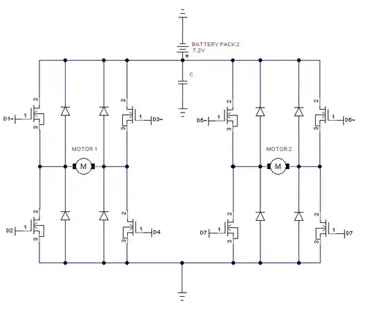
But your top mosfets have a problem. To turn them on their gates must be 5 Volt positive with respect to their sources. When conducting, their sources will be at +7.2V (minus a small drop), so their gates must be at ~ 12V.

Their are specialized chips that can do this for you (google "high side mosfet driver"), or you can use P mosfets at the top. But note that for such a P fet to turn off, its gate voltage must be 7.2V (with respect to ground), so you will need a 5v->7V level translation. This can be done by some transistors, or use a dedicatet chip (google mosfet driver).

You say you want to drive the mosfets from an arduino. I hope you are not going to use PWM? An Arduino output is bit to weak to drive a mosfet gate quickly. This is not a big problem if you switch the fet occasionally, but for PWM you'd better use driver chips.

Wouter van Ooijen
  • 48,407
  • 1
  • 63
  • 136
  • 1
    Someone in the comments section of the product page said "These mosfets are logic level mosfets and they have something similar to a charge pump built into them already, these will turn fully on when applying a 5v signal from a microcontroller," so I figured that it would work fine with my setup. – Michael Oct 14 '14 at 17:50
  • That person was unfortunately incorrect. There's no charge pump built into this MOSFET. I'm not sure I've ever seen a MOSFET with a built-in charge pump. It is, however, typical to see charge pumps built-in to MOSFET drivers. – Dan Laks Oct 14 '14 at 18:06
  • 1
    (extending Dan's comment) A typical high-side mosfet driver has such a charge pump built in. But do check: typically it must be used with PWM: it cannot just switch the top fet on continuously. – Wouter van Ooijen Oct 14 '14 at 18:15
  • The person in question also said that they switched a 7.3V power source with 5V from the Arduino using that MOSFET.. should I just assume that isn't true/possible? – Michael Oct 14 '14 at 18:19
  • That is true, but only when the source is at 0V which is not the case for your high side fets. And it will only work reliably for a low switching frequency. – Wouter van Ooijen Oct 14 '14 at 18:23
  • I see. Okay, looks like I'll have to look into getting a MOSFET driver. Thanks for the help! – Michael Oct 14 '14 at 18:40
  • @Michael do what Wouter implies and get a driver - the misinformation you collected is just that. – Andy aka Oct 14 '14 at 18:59
  • @Michael usually people use P channel Fets as the high side drivers to avoid this issue of gate voltage being higher than the source. – KyranF Oct 14 '14 at 20:35
  • @KyranF: call those high side FETs, not high side drivers, to avoid confusion with gate driver chips. – Wouter van Ooijen Oct 14 '14 at 20:41
  • 1
    @WoutervanOoijen ah true, every word counts when the poor guy is so confused. I shall edit! Oh no, it's too late. But yes, usually the high side FETs are P channel in lower voltage H bridges so that it can run off nice low voltages. Driver ICs can have internal high side gate drivers for N channel FETs by using charge pumps. – KyranF Oct 14 '14 at 20:41
  • Yeah :\ I was especially confused since my professor said we could just use N-MOSFETs for changing the direction of the motors and gave us the diagram: http://puu.sh/cbZV8/d98d0309a3.jpg without much explaining – Michael Oct 14 '14 at 20:59
  • @Michael you CAN. We are telling you that it's an issue of gate drive voltage, which in your situation provided in your question, you cannot deal with without a gate driver – KyranF Oct 14 '14 at 21:04
  • 1
    http://puu.sh/ccn3t/f587840192.jpg The motor here is connected to a 9V battery, and a regular N-MOSFET is used. Why isn't there a driver needed in this case? – Michael Oct 14 '14 at 21:15
  • Because there's only one MOSFET in that circuit and its source is connected to 0v - just like the 2 Low Side MOSFETs in your circuit. As everyone else has said, it's the 2 High Side MOSFETs which need a proper driver. – brhans Oct 15 '14 at 01:21
  • Ah, okay. That clears up my misunderstanding. Thanks for the clarification! I'll be buying a chip (https://www.sparkfun.com/products/9479) instead of making the circuit myself, so hopefully all goes well. – Michael Oct 15 '14 at 02:37