2

I'm new to this forum and I really don't know much about Audio Amplifier Circuits. Hope you can help me.

Here it goes:

VCC = +12, VDD = -12

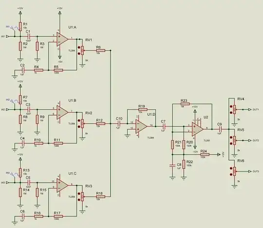
So basically what I'm trying to do is a circuit that mix 3 channels, amplifies them and then distribute them into 3 channels.

The problem is that when I test the circuit in real life I can only hear sound when I blow in my mic, anything like shouting singing or talking won't do any sound.

As I don't know much about audio circuits, I would love some help to solve this problem.

I'm currently testing with this:

Headphone

  • Driver: 40mm
  • Frequency response: 20Hz-20KHz
  • Impedance: 32 Ohms
  • Sensitivity: 90dB SPL/mW

Microphone

  • Pickup pattern: Cardioid (Unidirectional)
  • Type: Pressure Gradient Electret Condenser
  • Frequency response: 50-20KHz
  • Sensitivity: -40dBV/Pa re: 0dB = 1 Pa, 1KHz
  • Test conditions: 3.0V, 2.2K Ohm

But I want to be able to use any headphone or any microphone.

So my questions are:

  • Is the circuit OK? Do I have to change something?
  • What may be the reasons for only hearing when I blow on the mic?
  • Any suggestions?

How i solve those problems

  • The circuit is OK, i had to change the value of all the POTs from 50k to 5k, also all the polarized CAPs to non-polarized and reduce them from 47uF to 1uF all but the ones from the input, i change those for 10nF.

If you need any other info just tell me to add it.

Update:

Second Image

Now, In Proteus I'm losing the signal after the 5k POT. Whats happening?

POT losing signal A Signal is after the POT, while B is Before the POT.

Solved: the problem was Proteus it was bugged.

Update 2

Well now the circuit looks like this with most of the problems solved. Update 2

It works but now i have another problem, there is some background noise.

More Questions:

I'm testing the circuit in a Protoboard, moving it to a PCB changes anything? Is there something i should add or change to reduce this background noise? PS: when the mic is not connected or muted the background noise stops.

Solved

Had to take away resistor 24 from the 2nd update circuit.

JeremiasK
  • 35
  • 1
  • 6

2 Answers2

3

First question : What kinds of microphone? Common electret mics may need a bias supply, 1.5 or 3V fed through a 2 k to 10k resistor to bias them. (If you add this, also reverse the input coupling capacitors to their +ve terminal is positive!)

Second : what variety of opamp are you using? The +ve input is connected to ground via 1 megohm. The -ve input, via 1 kilohm. If the opamp is a type with significant input bias current (as low noise audio opamps usually are) this impedance imbalance introduces a significant input offset voltage ... multiply that by 100 and the opamp output may be sitting at a supply rail, clipping the signal. This is easy to diagnose with a DC voltage measurement on the opamp output. Reducing R2 to 1k would help (but load the microphone). Reducing the gain at DC, e.g. with 22 to 100uf in series with R4, R9,R14 would minimise this problem.

Any DC on the opamp output will create havoc with the faders RV1 to RV3 - loud noises as you fade... you probably want coupling capacitors between opamp and fader - OR reduce the opamp gains at DC as above, or possibly both.

UPDATE : Also, lose R20. It adds DC bias which would be important if the negative rail was 0V instead of -V, (i.e. single supply voltage) but if that was the case, all the other stages would need similar bias arrangements. ANd if it's an attempt to properly bias the electrolytic caps around that amp, ... well none of the other electrolytics have similar bias arrangements (and C12 is reversed!) As that stage also has a gain of 10, U2A output may be sitting at V+ at the moment (eliminating your audio signal)

3

First thing I notices is the time constant with your input capacitance and 1Mohm resistor - it's 47 seconds or equivalent to a high pass 3dB frequency of 0.0034 Hz.

This might take ages for your inputs to settle - make the input capacitor 47nF is my recommendation - this puts the high pass frequency at about 3.4Hz. Even a 10nF wouldn't be unreasonable (high pass of 16 Hz).

Your op-amp is a TL084 so I'm less worried about input current leakages causing offset voltage problems AND I'm happier with non-polarized caps at the inputs because if it is an electret mic and has a bias voltage on it, the electrolytic (have to be polarized correctly) input caps will become reverse biased and this may indeed be a possible reason why you see a problem.

Regarding your 50k pots, these will potentially give higher noise than say 5kpots and with 5k pots you can reduce R5, R10, R15 and R16 to something like 10ks also reducing noise. Noise is proportional to the square root of resistance so always best to go lower a bit if you can.

C7 and C12 are also problematic in the the signal they see may become reverse polarized. The time constants you are using around these circuits are very large given that those caps are 47uF - go for 1uF and non-polarized. U2 just appears to be a gain of ten stage so lose the centre biasing - 0V is centre and that is just fine assuming your Vcc and Vdd are largely equal and opposite.

You are using TL084 output amplifiers but this is really daft because you have an output pot that will likely introduce an impedance of about 25k (mid point). Just use pots and get rid of the extra 3 op-amps that feed the individual outputs. C9, C10 and C11 are not needed either or if you feel happier with them use non-polarized 1uF caps.

Andy aka
  • 434,556
  • 28
  • 351
  • 777
  • Thanks vey much i will try this tonight, can you tell me if POTs have to be LOG or linear? As the websites where i found this circuits dont specify it. – JeremiasK Oct 09 '14 at 22:11
  • 1
    This should explain: http://electronics.stackexchange.com/questions/101191/why-should-i-use-a-logarithmic-pot-for-audio-applications/101196#101196 - volume pots need to be log! – Andy aka Oct 09 '14 at 22:36
  • Ok, Out Pots should stay at 50k or 5k? – JeremiasK Oct 09 '14 at 23:12
  • 1
    A 50k pot will generate a johnson (thermal) noise of 4.02uV (over the audio spectrum at 20degC) which is pretty small but it's cool to be aware of it if you had a pot at the front end of a hi gain amplifier. See this calculator: http://www.sengpielaudio.com/calculator-noise.htm - i'd still go for 5k but, if you have 50k pots already suck it and see. The TL084 will self generate an equivalent input noise (over 20kHz) of 2.5uV so you've added a component that generates more noise that the op-amp you picked inherently does. – Andy aka Oct 09 '14 at 23:29
  • Wow, thanks for sharing, I prefer buying 5k pots as you recommended anyway i have to go and get more caps. I also have another question, Which non polarized caps are more suitable for my circuit? – JeremiasK Oct 10 '14 at 00:32
  • I added all the stuff you told me (Image on the post), don't know if im missing anything. But for some reason, when i simulate it in Proteus, i lose the signals after RV1, RV2, and RV3. Before there the circuit works – JeremiasK Oct 10 '14 at 01:18
  • The 10k resistors in the amp following the pots need to be much higher if using 50k pots. I think they were 100k before. Ceramic caps or polyester or polycarb... Virtually any non polarized caps will do the job but make sure the voltage rating is at least 50 volts. – Andy aka Oct 10 '14 at 07:33
  • Thanks again. About the other problem I'm losing the signal after the first 5k pots. The new Image is below after the full post. – JeremiasK Oct 10 '14 at 14:35
  • Also added another image showing you what i mean. – JeremiasK Oct 10 '14 at 14:55
  • Circuit Lab runs it perfectly, it seems to be a Proteus Bug. – JeremiasK Oct 10 '14 at 17:37
  • All works great and I added a new Update, can you help me with one last problem? (Update 2) – JeremiasK Oct 11 '14 at 19:01
  • My only observation is that R24 should be removed. It biases the output at half +V supply and loses you dynamic range. Also the bias resistors on the inputs, are they to power the electret microphones? – Andy aka Oct 12 '14 at 08:58
  • Yes the bias resistors on the inputs are there to power electret mics. Thanks taking out that resistor solve the problem. If some day i want to use the same circuit with only one power source what should i add? This would change the performance? – JeremiasK Oct 12 '14 at 15:20
  • It should be ok but better option is to use rail to rail op amps to give you more large signal swing. – Andy aka Oct 12 '14 at 15:24
  • Why did you ask about input bias resistors, is anything wrong with them? – JeremiasK Oct 14 '14 at 03:18
  • Sorry to rewarm this but I have a similar situation with distribution. Re. your last para. Why drop the 3 op amp buffers? Do they not provide channel separation when you're playing with an individual channel? And the TL081 data sheet suggests such @ http://www.ti.com/lit/ds/symlink/tl082.pdf for an Audio-Distribution Amplifier (Figure 27). – Paul Uszak Jul 01 '17 at 02:26
  • 1
    @PaulUszak Because the pots used negate the need for the three op-amps. Given also that all three op-amp outputs have exactly the same signal there is no channel seperation problem unless there is some requirement for driving individual lines but, then the pots are not helping drive three individual lines. – Andy aka Jul 01 '17 at 09:09