It appears that things are a bit more complicated than your quote from Wikipedia explains. The Wikipedia article doesn't appear to be entirely wrong, but it doesn't really explain things well either, as much as I hate to say this.
The long story short:
No, there will not be a distinguishable increase in voltage with signal reflections as far as the collision detection is concerned, because the collision detection looks at a filtered, low-frequency result of the signal.
Yes, the voltage will increase during true collisions, that is: When multiple nodes are transmitting at the same time.
From my experience, on a typical setup with a missing termination or an impedance mismatch, the collision detection will become active before the signal becomes too broken for the receiver to decode it properly.
Here are the details:
To start, here's an oscillogram showing the signal on a 10base2 line when being flood-pinged (e.g. # ping -f 192.168.1.something). The large signal is from the transmitter close the the oscilloscope, and the smaller signal originates from the far end of the cable and has already been damped by approximately 10 m of coax.
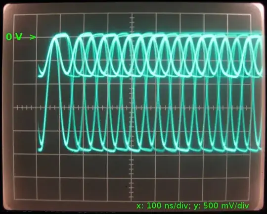
Note: 10base2 will drive the cable using a negative signal; it's not an error that the 0 V marker is near the top of the screenshot.
Back to how collisions are handled:
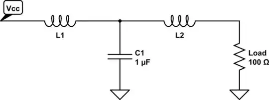
Reflections of the AC signal (which is a Manchester-code 10 MHz signal that looks a lot like a 20 MHz signal when busy) are one thing, but from what I've read recently, the collision detection circuit does not look at individual edges of the AC signal only. Instead, the signal on the BNC end of the interface, which may be any combination of the transmitted signal and received signals from other network nodes, is filtered into the AC component and a DC component.
Then, the DC component is inspected and evaluated for possible collisions. This is where the requirement for a minimum packet length comes from; if a transmitter was allowed to send a short 1 bit-packet, there wouldn't really be a DC component for the short length of the single pulse. In the very strict sense of the definition of "DC", an average current for the length of any packet is still not a constant, never-ending DC signal, but you get the concept.
Also, it is good to know that 10base2 and 10base5 don't work using voltage levels being applied to the coax cable, the transmitters are actually current sources. Now, even though fancy radio frequency reflections and transmission line theory surely does apply for any ethernet medium, and 10base2 and 10base5 tend to be some of the standards most sensitive to these issues, the main reason why reflections and proper termination matter is the fact it uses current sources. Eventually, what the receiver will want to evaluate when detecting the signal are voltage levels, and from a DC point of view (collision detection!), it is the terminating resistor that will turn any transmitted current into a voltage, using the all familiar equation Vreceived = Rtermination × Itransmitted.
Now, think of two nodes transmitting packets at the same time (read: applying current into the terminated coax line). The current into the termination would be twice as high as the specification allows, and the voltage resulting on the terminating resistors would be Rtermination × 2Itransmitted = 2Vreceived. This would be detected as a collision behind the DC (or low-frequency) end of any receiver.
Likewise, if you doubled the value of the termination, you would end up with a voltage higher than desired: 2Rtermination × Itransmitted = 2Vreceived. Even worse with an infinite (missing) termination resistor; resulting in a voltage as high as the supply rails of the transmitting current source will allow...
With 10base2/5 getting into the years, it isn't really easy to find good references on how things work (and the explanation that uses RF reflections only is really all to easy to believe!). However, there is one chip that was used quite ubiquitously (*83*92*) and got cloned by many manufacturers in many variants. The many data sheets and application notes for these chips have some good explanations.
Most notably: "DC LEVEL: The DC component of the signal has to be between 37 mA and 45 mA [during the length of a packet]. The tolerance here is tight since collisions are detected by monitoring the average DC level on the coax [again: during the length of a packet]." (Source: p.4 in National Semiconductor, Application Note 442, Alex Djenguerian, June 1986, Ethernet/Cheapernet Physical Layer Made Easy with DP8391/92; also backed up by this data sheet)
To make things a bit clearer, here's a picture of the coaxial transceiver interface (CTI) of a typical chip, taken from National Semiconductor's Application Note 442:
The transmitter will sink (negative signal!) current through the diode from the coax. The diode may be omitted for 10base2 because it's only there to decrease the capacitance imposed onto the cable by the chip's internal circuit.
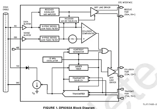
In the DP8392's block diagram from TI, formerly National, with the coax on the left, now, you can see how the AC signal is forwarded to the actual receiver (which would be the block affected most by unwanted reflections), and how the signal is also run through a low-pass filter, extracting the (so-called) DC-component for collision detection.
Now, for the high-frequency, AC part of the signal, you do see an overall increase in peak-to-peak amplitude when you have reflections on your cable:
This effect might lead to a garbled signal that may not be understood by the receiver. Collision detection, however, and as explained above, will look at the averaged-out (filtered) part of the signal, and won't care much about the spikes caused by the reflections.
Personal note: Even though this stuff is becoming obsolete (see the faint watermark in the block diagram from the data sheet above ;-), I am quite fascinated by everything that went into it and I wish I had the time to build such a transceiver from basic blocks like OpAmps, glue logic and individual transistors and passive parts. Like, ... Now!