According to the datasheet, SDINx signal have an internal pull-down, so you can leave the pin unconnected.

For the AD2/SDOUT2 you'll need to put a pull down or pull up resistor as it will set the I2C address. And as you don't use the SDOUT2, you will only have your pull up/down resistor.
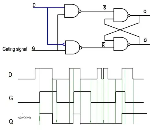
Latency is the time between the signal enter the chip and when it will go out.
The "normal" path is in blue on the previous figure. You can do a lot of transformations on the signals but the latency can be high.
4.6.3 DAC1-4 Path
The DAC1-4 path includes a programmable group delay which delays the output audio signals to allow the DAC5 output to operate in feed-forward fashion, adjusting the voltage rails of the tracking power supply in anticipation of the coming audio signal
The group delay can be between 0 and 500 µs to adjust with the DAC5.
And the detail for Low-latency path in green:
4.6.4 Low-Latency Path
A low-latency path is provided to allow four user selectable data signals to be routed around the group delay block and interpolation filters of the DAC1-4 path. These four signals can be present in any of the 32 slots on the two TDM streams on SDIN1 and SDIN2.
Finally from the characteristics:
The DAC1-4 path is quite longer than the low-latency path (11/Fs against 2/Fs in single speed mode) due to the interpolation filter. The DAC5 path is adjustable to have a latency equal to the DAC1-4 path or the low latency path.
Be careful to the Note 24 which state that you need to add the "Group Delay" (first block of blue path) to the specified delay.
EDIT : (forgot the address at startup)
For the AD2/SDOUT2 signal, when the internal reset signal of the chip is going inactive a small circuit will check the "value" of the AD2 input. This only occurs at the startup phase of the chip, after the startup is finish, the pin will be "tied" to SDOUT2 signal.
This is a kind of a mux working at the startup.
Many chips having an I2C bus use this trick to allow users to configure the address without adding multiple address pins. Some will even use +VCC, GND, High-Z, pull-up or pull-down "sense" to offer up to 5 configuration of address with one pin.


