How can I regulate duty time and frequency of 555 timer output with 2 potentiometers?
Asked
Active
Viewed 5,412 times
3
-
By steering the charge and discharge currents. – Ignacio Vazquez-Abrams Oct 02 '14 at 18:51
-
i'm so nooby i know that i need control capacitor charging time and discharge time with those resistors... maybe someone can draw schematic? i googled a lot and just founding duty cycle regulators or freq.. but no one in same layout. – Klasik Oct 02 '14 at 18:55
-
So then examine the two and put them together. – Ignacio Vazquez-Abrams Oct 02 '14 at 18:57
-
i think its impossible :) to duty cycle used 7 - discharge as output... in freq... using 3 output as output – Klasik Oct 02 '14 at 19:00
-
3Ouch, @Klasik, please use capitalization to make your comments easier to read. – JYelton Oct 02 '14 at 19:49
-
I don't think that is possible. But it would be easy with any small microcontroller :) – Wouter van Ooijen Oct 02 '14 at 20:32
1 Answers
7
Using two pots to adjust the frequency and duty cycle is easy, but there may be interaction between the controls. The simplest method is to have one pot for charge and another for discharge, with diodes steering the current between them. To change duty cycle you turn one pot up and the other down. To change frequency you adjust both in the same direction. That's a lot of interaction!
You can rearrange the pots so one controls duty cycle and the other changes frequency, but there will still be some interaction. Here's a circuit which has minimal interaction and provides a duty cycle range of about 2~98%. The practical frequency range is only about 3:1, and is quite sensitive at the low end.
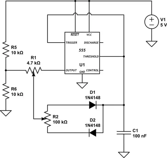
simulate this circuit – Schematic created using CircuitLab
However there is a way to get wide frequency range with 0~100% duty cycle and no interaction, using the same number of parts! It uses the 555 as a triangle wave generator, and an opamp or comparator to control the duty cycle.
Bruce Abbott
- 55,540
- 1
- 47
- 89
-
My son has asked for some help with a school project, building a dc motor controller. We decided to use the lower of the two circuits. We got it working as displayed, but cannot get the duty cycle to 0- it is stuck on the low end at 160 uSec. Top end is fine at 99% duty cycle. Only changes are elimination of R1 to set the frequency at 1kHz and using a UA741CN Op amp in lieu of the MCP601. I have tried reducing the value of R5, with no effect! Any ideas? – user218517 Apr 15 '19 at 20:39
-
@user218517: Your biggest problem is the [741 opamp](https://electronics.stackexchange.com/q/304521/11683). It is simply not designed to work from a 5V power supply -- it requires a minimum of 20V for proper operation. – Dave Tweed Apr 15 '19 at 21:29
-
I don't get how this setup can set the duty cycle in so wide range. If I get it correctly, the voltage on the positive input of the opamp can be set between 1/3 - 2/3 Vcc. To be able to set the duty cycle in range 0-100% I would expect this voltage between 0 - Vcc. – Katona Sep 12 '20 at 20:34
-
As the pot voltage changes it crosses the triangle wave at a different height, which equates to a larger 'on' time as it moves towards the apex. Above 2/3Vcc the PWM is fully on, and below 1/3Vcc it is fully off. The pot voltage only has to cover that range, which is why R3 and R4 are there (otherwise the pot would only be effective in the middle of its range). – Bruce Abbott Sep 12 '20 at 22:50
-
Sorry, I have no electrical engineering background, but does that mean the triangle wave alternates in the 1/3 -2/3Vcc range and not in 0 - Vcc? – Katona Sep 13 '20 at 11:09
-
Yes. The 555 charges the capacitor when it goes below 1/3 Vcc, and discharges it when it goes above 2/3 Vcc. – Bruce Abbott Sep 13 '20 at 20:53