1

I want to reverse the polarity of my current source, which is a capacitor in this case, in the middle of discharging phase. Also the capacitor bank is being discharged through a coil to make a short time electromagnet. What I want is to reverse the polarity of that magnet in middle of discharge. How can I achieve this using MOSFETs or other fast switching components?

Below is the single polarity simple circuit. Also I'm using polarity sensitive capacitors in my capacitor bank.

I know that H-bridge would be the component in this situation, but I'd like to build my own "H-bridge" using n- and p-type MOSFETs to handle these high currents.

schematic

simulate this circuit – Schematic created using CircuitLab

JYelton
  • 32,302
  • 33
  • 134
  • 249
  • What voltage are you charging the capacitor to? At what point in the 'middle of discharging phase' do you want it to switch? What is the resistance of your electromagnet? What is the purpose of the 1N4148 diode? – Bruce Abbott Oct 02 '14 at 05:28
  • @BruceAbbott I have an incoming low voltage signal to indicate when switching is required. Diode is there just to protect the polarity sensitive capacitor from being damaged after the electric field collapses when capacitor runs out of electricity. – The amateur programmer Oct 02 '14 at 05:32
  • 1
    It is more likley that the coil will generate enough volatge to kill the diode. You will need some path for the coil current to dissipate the energy stored in the coil. – Wouter van Ooijen Oct 02 '14 at 07:55
  • As for your main question: have you considered a H bridge chip? a DPDT relay? – Wouter van Ooijen Oct 02 '14 at 07:55
  • Reversing the polarity of the electromagnet whilst it is being fed current in one direction will generate a massive voltage pulse. V = L\$\dfrac{di}{dt}\$ and di/dt is going to be massive hence V is going to be massive. Are you sure you know what you want to achieve? – Andy aka Oct 02 '14 at 07:58
  • Yeah, inductance in a coil will resist the current change with lots of voltage as mentioned by others. Fireworks are gonna be pretty – KyranF Oct 02 '14 at 08:55
  • @KyranF Ummh... So I should dissipate the energy stored in the coils magnetic field before applying current in another direction? – The amateur programmer Oct 02 '14 at 10:43
  • 1
    You need some serious [high voltage diode based] clamps which will shunt (redirect) the current and voltage during the inductive voltage spike, while keeping it hopefully as close to the intended voltage level as possible – KyranF Oct 02 '14 at 11:22
  • @KyranF Would using a Transient voltage suppression diode suffice for this clamping purpose? – The amateur programmer Oct 02 '14 at 12:35
  • Not really, TVS diodes are fast-acting for pulsed voltage spikes, such as lightning strikes, ESD (better to use actual ESD diodes though) and short term low "power" spikes from really noisy supplies like car alternators. You need some pretty uber diodes for extended periods of over voltage clamping while the coils change direction – KyranF Oct 02 '14 at 12:47
  • I don't see what all the fuss is about. Probably *most* H-bridges drive inductive loads. We call them motors. There are no fireworks, crazy high voltage diodes, or TVS. – Phil Frost Oct 02 '14 at 19:26

1 Answers1

3

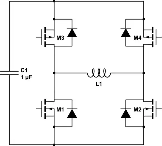
Here's a basic MOSFET H-bridge:

schematic

simulate this circuit – Schematic created using CircuitLab

It's more common for L1 to be a motor, but as far as the H-bridge is concerned, an inductor is the same. A motor is just an inductor that happens to produce mechanical motion.

There are many ways you might drive these MOSFETs. Search for H-bridge drivers at your favorite electronics supplier: they are commodity components. Proper selection is not a trivial topic. I suggest:

If switching speed is not critical, you may be able to the MOSFETs directly with a microcontroller. Also you could consider a discrete driver.

Note that the diodes drawn need not actually be diodes, they can be the inherent body diode of the MOSFETs if your design parameters allow. There will be current in the diodes only transiently as the H-bridge is changing states, so depending on how fast the switching is, and what the current in that time is, you may remain within the MOSFET's operating parameters. Read the datasheet.

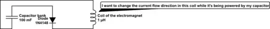
The rate at which you can reverse the current in L1 is limited by the inductance and the voltage you can apply to it (in this case, determined by C1). This is a fundametal property of inductors:

$$ v(t) = L \frac{\mathrm di}{\mathrm dt} $$

It follows that if you want to reverse the current very quickly, you must minimize inductance and maximize voltage.

Also bear in mind that when you change directions on the H-bridge, the inductor will reverse the direction of current in the capacitor and charge it. This will continue until the current has decreased to 0, at which point the capacitor will start discharging and current will start flowing in the opposite direction.

Phil Frost
  • 56,804
  • 17
  • 141
  • 262
  • What do you think about adding two zener diodes to short out the voltage spike during switching? Also my capacitors are polarity dependent (electrolytic) so the spike coming back to the capacitor charging it with wrong polarity wouldn't be good. – The amateur programmer Oct 04 '14 at 09:47
  • Also is the current coming from c1 to the coil in this schematic? – The amateur programmer Oct 04 '14 at 09:47
  • @Theamateurprogrammer, the diodes in the schematic already clamp the voltage to within 0.65V of the supply rails. Zener diodes would add nothing. Also, the *voltage* polarity is the significant thing on electrolytic capacitors. When you switch the H-bridge, the voltage polarity remains the same. The direction of current reverses. That's not a problem: it's no different than how capacitors are normally charged. – Phil Frost Oct 04 '14 at 13:29