3

I'm trying to find the Thevenin equivalent for part A of this circuit: enter image description here

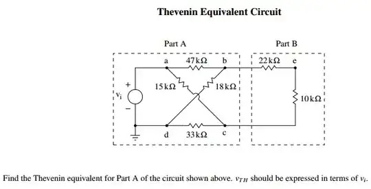
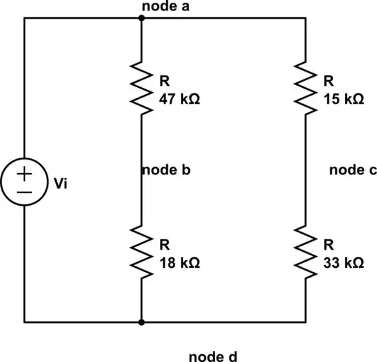
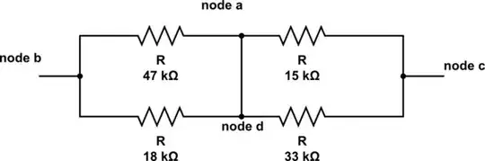
I begin by opening the circuit at the dotted line of part A. Then I try to find \$V_{oc}\$ across the two terminals that are open. I can see that the 47kΩ is in series with the 18kΩ since no current flows to the open circuit, and that the 15kΩ is in series with the 33kΩ. However I'm having a lot of trouble redrawing the circuit. Not really sure about how to make it look simpler. Any ideas?

Nick Alexeev
  • 37,739
  • 17
  • 97
  • 230
user3266738
  • 215
  • 5
  • 10
  • 1
    It might help if you draw the four resistors in Part A as a Wheatstone Bridge, with Part B in the middle of the bridge. Then, you can treat the left and right sides of the bridge as separate Thevenin sources, which you can combine to come up with the Thevenin equivalent of the entire network. – Dave Tweed Oct 02 '14 at 04:40
  • Related: Star-delta and delta-star transforms will sometimes make such things easier. | Recognising that this can be redrawn as a "bridge" circuit (as others have said) may help. – Russell McMahon Oct 02 '14 at 11:23
  • 1
    The "crossover" is just to obfuscate the circuit and make you think a little. Flip the 33 kOhm resistor horizontally and you have a square of resistors. The rest should be obvious from there. – Olin Lathrop Oct 02 '14 at 13:04

2 Answers2

5

It may not look like it because of the crossover, but the resistors in Part A actually form two independent voltage dividers. Redraw the circuit so that all the resistors are going vertical between the + and - wires, and points b and c are in line horizontally. Now it should be obvious.

Bruce Abbott
  • 55,540
  • 1
  • 47
  • 89
3

You must redraw the circuit to obtain the Thevenin's voltage:

schematic

simulate this circuit – Schematic created using CircuitLab

Then you must find the voltage between node b and node c. Passivating the source Vi, you find the equivalent resistance:

schematic

simulate this circuit

Between node b and node c.

PeterJ
  • 17,131
  • 37
  • 56
  • 91
Martin Petrei
  • 3,034
  • 12
  • 20
  • I agree with your top diagram, but the bottom diagram doesn't model the resistance seen between nodes b and c. Series combination of resistors in parallel is not the same as parallel combination of resistors in series. – Olin Lathrop Oct 02 '14 at 13:02
  • @OlinLathrop: You're wrong, that is the correct model for the source resistance between those two nodes. – Dave Tweed Oct 02 '14 at 13:10
  • @OlinLathrop I do not understand what you raise. The second diagram corresponds to the equivalent circuit with the passivated source; as it is a voltage source, was replaced by a short circuit. – Martin Petrei Oct 02 '14 at 13:27
  • @Dave: It is now. It wasn't before the edit. I'll remove the -1 now that the anwer has been fixed. – Olin Lathrop Oct 02 '14 at 14:00
  • Argh! It won't let me remove the downvote. Apparently the answer was being edited as I wrote my comment, and the system thinks I voted since the last edit, so won't let me undo it. I don't see why the system won't let me. What's wrong with changing one's mind, possibly swayed by someone's argument in a edited question or a comment? – Olin Lathrop Oct 02 '14 at 14:02
  • @OlinLathrop, an accepted workaround (although I agree it should be OK to change your mind in the first place) seems to be to do a minor edit. I just did one so you should be able to undo it now. – PeterJ Oct 02 '14 at 14:14
  • @OlinLathrop It has also happened to me with another question, but after about 30 minutes, if I click on the down arrow, run a "undo" for the downvote. It's ok. When I did the wiring diagram, I forgot to short the nodes of voltage source, then I edited. You've probably seen the first version. :) – Martin Petrei Oct 02 '14 at 14:14
  • @Peter: That worked, downvote undone. Martin, after 1 hour it won't let you change your downvote without the question being edited. Apparently even a trivial edit is enough to allow you to change your vote. – Olin Lathrop Oct 02 '14 at 14:29