4

I've got this circuit with 3x atmega328 & nrf24l01+ running off shared power supply, either 2x AA battery or 3v3 reg.

It acts as a repeater, and depending on the origin of the message and the destination it could be passed through all 3 radios on its way. And sometimes when I send signals through it, they don't get to their destination.

Generally at higher PA (power amplifier) settings it is less reliable, though I don't think its RF interference as I have tried them at varying distance from with each other with little change. Also if I run all 3 separate on their own batteries, I can have them as close as I can get, right next to each other and it works fine at max PA.

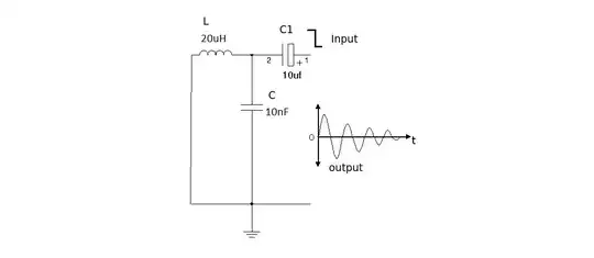
I think it is more power related. I have tried big electrolytic cap on power supply and 100nF on the module them self.

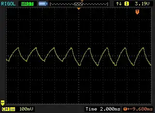
On my scope I have seen various interference pattern in the voltage supply, as pictured.

Generally I see patterns like this at same time message have trouble reaching their destination.

One radio/328 by itself is not a problem, it seems when they all run off the same supply each of their individual ripple is combined to make something that has effect.

I am hoping someone can look at the capture and recommend something?

*edit, added 2nd grab.

100N cap:

100N cap:

470uf cap:

enter image description here

2x470uF on each, scope on cap leg:

enter image description here

enter image description here

Scott Seidman
  • 29,274
  • 4
  • 44
  • 109
Hayden Thring
  • 361
  • 5
  • 20
  • 1
    millivolts, microvolts? – Andy aka Sep 29 '14 at 10:08
  • 100 milli volt vertical scale – Hayden Thring Sep 29 '14 at 10:38
  • It could be a measurement problem, it could be a connectivity problem, it could be a circuit problem or a layout problem. Start by showing a circuit and how things are connected. – Andy aka Sep 29 '14 at 11:45
  • 1
    they are huge time periods though, 2ms per horizontal division. They are also very digital-looking. I suggest you put much more than 100nF capacitance at each module. – KyranF Sep 29 '14 at 12:16
  • 1
    @KyranF I just tried 470uF's and you can see the different waveform above. – Hayden Thring Sep 29 '14 at 13:26
  • @HaydenThring alrighty then, whack 1-2 of those for EACH module, right at the supply input, and if you can also get a 1000-2000uF bulk capacitor on the supply as well will probably fix all the issues. It seems you have some serious supply decoupling issues- either from long wires from the source going to each module, or just from heavy loading without any reasonable nearby capacitors. Can you also please make sure you show the waveform of a point measured as close to/on the module/s as possible? – KyranF Sep 29 '14 at 14:46
  • @KyranF, It tried 2 on each, which seems to have reduced the wave peak some, and it seems more reliable. I have added 2 more grabs. I also tried a 2000uF but no effect. Im not sure if what im capturing is a problem or a symptom of one. – Hayden Thring Sep 29 '14 at 21:47
  • @KyranF, Also the 2 new grabs where made at the cap leg attached to radio voltage supply. – Hayden Thring Sep 29 '14 at 22:02
  • @HaydenThring Because the drain seems to be a long DC event, I guess the supply and the resistance over which the current is flowing just happens to lose 100mV no matter how many caps you put on it. Does your equipment operate as intended now? Do you still get losses/faulty behaviour? – KyranF Sep 30 '14 at 05:23
  • Ive got it pretty good by putting a 470uF on the radio and adding a 470uF on the 328 (already has 100N), and by also limiting my power usage/output but running only the uplink unit (longer distance) at max power and the other 2 local units (shorter distance) at low/med power. I even tried 4700uF on the radio (not much improvement) and a 1F on the power (no improvement), it was putting an extra one on the 328 that really helped. But i will still likely experiment to see if it can get any better... – Hayden Thring Oct 01 '14 at 23:08

1 Answers1

1

Did you try LC filters out?

I am a little rusty on RFI & EMI, but here is what I would try.

Background Logic:

Depending upon the frequency of the uC & of course other crystal oscillators in the circuit, it could be possible that either power supply is giving up or the capacitors are unable to filter the ripples out.

The capacitors don't always have ideal frequency response as negative slope. In particular electrolytic capacitors may behave differently at different frequencies. At higher frequencies, they may even behave as inductors. Refer to Frequency dependence of electrolytic capacitors for similar discussion.

Experiment:

I think I would try a combinational solution: a set of electrolytic capacitors, ceramic & polyester capacitors in parallel with each module in LC combinations. Each module has at least one inductor in series, two or three parallel capacitors of different kinds, that is.

Vasu
  • 129
  • 5
  • Thanks, I will look into these variants of caps, what do you mean by LC ? – Hayden Thring Oct 01 '14 at 23:12
  • Inductor (L) - Capacitor (C) filters. I know three models, Series L with parallel C, 'T' & 'pi' models. Refer this page: http://www.radio-electronics.com/info/rf-technology-design/rf-filters/simple-lc-highpass-filter-design.php. – Vasu Oct 14 '14 at 07:59