1

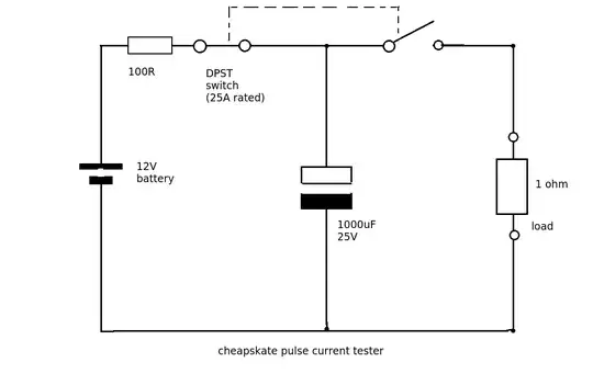
How could I, a cheapskate hobbyist, generate large currents around 8–10 Amps to run through a short circuit? That is, the objective is to stress test a very low-resistance circuit going through relays, wires, and connectors, all rated for 10 A / 250 V or more.

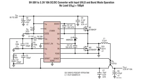
For example, would it be feasible to build a high-current, low-voltage switch-mode supply?

The load circuit's total resistance will be less than 1 Ω — hopefully a lot less, since at 10 A that would still consume 100 Watts.

I know that people have rewound transformers for huge currents and tiny voltages to melt metallic objects, but that seems hard to do and to control (though I suppose a dimmer on the primary side would do it).


I realised that I could just power a toaster, hot air gun, etc. from mains through the circuit. I would first measure a suitable combination using a power meter, so that the load is e.g. 2300 W when I want 10 A (at 230 V). But this will make noise and heat up my home, so the testing would have to be relatively short-lived. I'd still be interested in a more elegant, laboratory-style solution :-)

PeterJ
  • 17,131
  • 37
  • 56
  • 91
Rennex
  • 690
  • 4
  • 9
  • 1
    This doesn't answer your question because you've asked for a SMPS but maybe you could use a Ni-MH D cell or two depending on the duration of testing? Plus they and the charger might be useful for other stuff. – PeterJ Sep 29 '14 at 12:41
  • @PeterJ: That actually does answer it; feel free to move your comment into an answer :-) Maybe the question wasn't as clear as it could be; the SMPS idea was kind of a sub-question, and the main objective is to push about 10A through a low-resistance load. (And mods seemed to be confused about this too :-). Anyway, I hadn't realised you can draw 10A from those D-cells **for like an hour**, so that's a viable option too! – Rennex Sep 30 '14 at 04:47

2 Answers2

2

Yes, it's feasible to make such a supply. In my experience bench switching supplies don't like to output less than a volt or two, but such a supply could be designed.

A faster, and probably cheaper, approach might be to repurpose a cheap PC power supply. A $15 supply would likely be able to output 15A on the 3.3V or 5V rail, so if you add a series resistor you can get a more-or-less constant current. The PC supply provides isolation for safety, so even if you made your own supply it would be a convenient place to start.. You have to ground a wire to get the supply to start and to provide some load (10W resistor) on the 5V rail - do a search for details.

If you use a chassis-mount 0.33Ω or 0.5Ω 50W resistor that will cost about $5 so total cost could be under $20 especially if you scavenge the supply. Be sure to bolt the resistor to a suitable chunk of metal to act as a heat sink, perhaps using a small 12V fan powered from the PC supply.

If you are dead set on making a SMPS for whatever reason, I suggest you start as above, but use the 12V output and a decent controller chip such as an LT3800 which uses external transistors. It's not as easy as it looks, and it doesn't look all that easy. If you add a 0.12 ohm 15W sense resistor it can be coerced into outputting 10A constant current, but add a diode and resistor to keep the output voltage from getting too high with no load. With a few more parts to shift the feedback voltage upward, the sense resistor could be reduced to a smaller, lower power, part. If the latter makes no sense to you, there will probably be difficulties (many ruined parts) in getting this to work. 10A is a fairly high current and even small inductances can cause problems. http://cds.linear.com/docs/en/datasheet/3800fc.pdf

Rennex
  • 690
  • 4
  • 9
Spehro Pefhany
  • 376,485
  • 21
  • 320
  • 842
  • You're right, a PC power supply is a good and simple solution. One in my old PC promises over 20A on the 5V and 3.3V lines, and some 30W of heat isn't that difficult to get rid of. This solution just requires choosing the power resistor based on the load resistance (or using a well-cooled linear regulator) to control the current. The SMPS idea was just to minimize heat loss while adapting to various loads, but it might be needlessly complex for this use. – Rennex Sep 30 '14 at 04:36
1

If you can be satisfied with just a short pulse of current then try this.

enter image description here

The capacitor is charged up through a 100 ohm resistor for a 10 or 12V supply. Even a few AA size batteries in series would work as the charging current is quite small. When ready to test flick the switch. This opens the charging circuit and disconnects the battery. A pulse of current = Vc/1 ohm will initially flow. For a voltage of 10V and a load of 1 ohm this gives you a 10A pulse. This will discharge the capacitor after about five time constants (about 1 mS).

For an even cheaperskate circuit use a SPST switch and keep the battery in circuit. The 100R resistor will limit the current taken from the battery.

JIm Dearden
  • 18,926
  • 30
  • 40
  • Thanks, I like that answer! It's easy to add more capacitance for longer pulses, and the peak current can be (roughly) controlled by charging the caps to a chosen voltage, if the actual load resistance has been measured. However, I think this stress testing does call for more sustained current. – Rennex Sep 30 '14 at 03:55