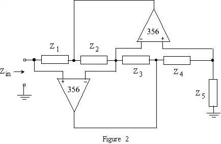
Can anyone give an explanation about general impedance converter? This question might not be specific enough, but I will appreciate if someone could share as much as possible about this circuit.

Can anyone give an explanation about general impedance converter? This question might not be specific enough, but I will appreciate if someone could share as much as possible about this circuit.

As George noted in his comments, if you label the nodes 1-5 from left to right, nodes 1,3 & 5 are all the same voltage due to the op-amps forcing enough current until those nodes are equal.
Node 1 would also be known as the input voltage. Notice that the output current is Vin / Z5 then. Which is also equal to the current through Z4.
Note that the current through Z2 and Z3 have to be equal to eachother. From the information so far, you can determine the voltages at nodes 2 and 4 with respect to Vin. Once you know node 2 voltage, you know the input current (Vin-V2)/Z1. The output current is in terms of Vin. If you divide the output current by the input current, you'll know the difference in impedance because the equations will be true over all Vin. That is, Vin/Iin / Vout/Iout = impedance_conversion. Vin=Vout in this case, so Iout/Iin = impedance=conversion.
Working through what I just described you should end up with this:
$$ Iout=Vin/Z5 $$
$$ V4=Vin+Vin/Z5*Z4 $$
$$ V2=Vin + (Vin-V4)/Z3*Z2$$
$$ (Vin-V2)/Z1=Iin$$
$$ \frac{Iout}{Iin} = \frac{\frac{Vin}{Z5}}{\frac{Vin-V2}{Z1}} = \frac{Z1}{Z5}\frac{Vin}{Vin-V2}$$
$$ = \frac{Z1}{Z5}\frac{Vin}{\frac{-Vin+V4}{Z3}Z2} = \frac{Z1Z3}{Z5Z2}\frac{Vin}{-Vin+V4}$$
$$ = \frac{Z1Z3}{Z5Z2} \frac{Vin}{\frac{Vin}{Z5}Z4} = \frac{Z1Z3}{Z2Z4} $$
$$ \frac{Zin}{Zout} = \frac{Iout}{Iin} = \frac{Z1Z3}{Z2Z4} $$
If the impedances are just resistances I can't imagine it being terribly interesting as it's just a resistor made up by 4 resistors.
If the impedances are capacitive and resistive and you place them right, you could potentially get an impedance that looks like an inductor. This has an interesting potential usage. In integrated circuits, capacitors are much prefered to inductors due to their small size. Now you can make a circuit that acts like an inductor without an inductor. It can also be tuned and altered using the resistors and capacitors so that sizing can be optimal for a chosen inductance value. This has applications in integrated filters and probably other integrated circuits.
This should be enough to get you started on this topic. You should probably read up on gyrators if you're interested in this more. Hopefully I didn't make any typos in all of my equations.
Another way of looking at the result is this as Z5 = Zout: $$ Zin = \frac{Z1Z3}{Z2Z4}Z5 $$ So Z5 can be used as just another knob to adjust the impedance you're creating.
I think, this is not the right place to explain how the GIC works - nevertheless, some general remarks:
The GIC topology as shown was invented by A. Antoniou in 1969 (!). For a specific dimensioning some non-ideal opamp properties cancel each other.
The working principle of the GIC can be derived from a series connection of the two different forms of a negative impedance converter (NIC).
The GIC das been proven as one of the most versatile active circuits and is extensively used in active filter and oscillator circuits. GIC applications include active (lossless) L-simulation as well as FDNR realizations (frequency-dependent negative resistor). For this purpose, the various impedances Z are chosen as R or 1/sC, respectively.
Adding to what Horta wrote...
If you make Z4 a capacitor, then Z4 becomes 1/sC. So the impedance becomes:
Zin = s (Z1 Z3 Z5) / Z2
Which is an inductor of value Z1 Z3 Z5 / Z2
If we replace Z5 with a trim pot, then we have a variable inductor...