I am trying to modify a SWR meter (http://www.mondoplast.ro/Reflectometru-powermetru-Performer-DF2469-pg_ft-3597) and add a new scale (now it has 200W/50W and 20W/5W) for 2W/0.5W.
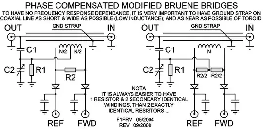
I have made some measurements and it does not work exactly how I expected so I am stuck... The SWR meter is a cross needle Ampere meter (100uA) with 1,8k ohms internal resistor. In the directional coupler is only 1 shunt resistor of 150Ohms.(the schematic for the coupler is similar with the one in the left (http://f1frv.free.fr/main3h_SWR_Bridges_fichiers/DET_bridge_R2.png)) The scale selector adds a capacitor between the FWD/REF line to the ground in the peak position:
FWD:
200W 220uF
20W 100uF
REF:
50W 100uF
5W 47uF
(here I expect this to be for the average not for peak... ) And also adds in the FWD/REF line a series resistor:
FWD:
200W - 145,5K
20W - 33,4K
REF:
50W - 54,5k
5W - 12,5k
(Actually in the schematic there is a fixed resistor an a variable one in series, here is the measured value of the resulted resistor) What values of resistors should I put for 2W/0,5W. (I expected that the resistor to variate linear eg. 200W 145,5K 20W 14,55k) Can you please help me or at least send me to a documentation of how a SWR circuit/bruene bridge works. Thank you, Bogdan