6

This is a long post as I want to take you through all the work I've done. The TL;DR version is I've got an unknown controller for a mechanical heat pump and I'm trying to reverse engineer the signal and data....so if you think you can help, then please read on.

First off, I'm not an electrical engineer. I'm a software engineer who is a bit out of his depth.

I have an ITS heatpump and it has a controller I want to reverse engineer in order to read data from the sensors and set some parameters in software. I've looked for technical specifications and asked the manufacturer, but they told me to GTFO. In the end, reverse engineering seemed the only way to get what I wanted.

Between the unit and the control panel is a 3 wire connection. From what I've been able to deduce it is GND, +12V (to power panel) and a signal wire.

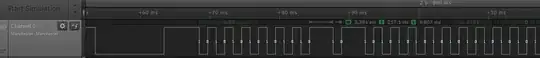
I then got myself a Saleae protocol analyser to see what I could see. I've confirmed that the single data wire is used for both RX/TX. I thought the easiest point to tackle is the control panel and disconnected the signal wire so that I could read only what the panel is transmitting. A sample can be found at http://tinyurl.com/ppuemv7 . I am using the 1.1.24 beta version for decoding. It seems to decode nicely using Async Serial 8N1 autobaud. I've tried a bunch of other decoders and parameters but all of them get framing or other errors.

I then started systematically changing the values on the controller to see how the byte stream changes. I changed parameter 1 using values [51-55] and this was the result (spaced intentionally for ease of spotting differences) of the byte streams.

Format <Param>-<value>:<decoded byte string in hex>
01-51:8055DD555555555555555555555555555575577557F58075757757 DD 757577577755DD55555D7777775577755D 55 5D 77 FD
01-52:8055DD555555555555555555555555555575577557F58075757757 D5 DD7577577755DD55555D7777775577755D 55 77 77 F5
01-53:8055DD555555555555555555555555555575577557F58075757757 5D DD7577577755DD55555D7777775577755D 55 75 77 FD
01-54:8055DD555555555555555555555555555575577557F58075757757 75 DD7577577755DD55555D7777775577755D 55 D7 77 F5
01-55:8055DD555555555555555555555555555575577557F58075757757 DD D757DD5D7755D757555D75DD7755DDD575 57 D5 77 57

From that the pattern wasn't obvious so I decided to change another parameter (param:0 changed to 16 from 15) keeping parameter 01 at 52 and this is what I got.

Format <Param>-<value>:<decoded byte string in hex>
00-15:8055DD555555555555555555555555555575577557F5807575 7757 D5 DD7577577755DD55555D7777775577755D 55 77 77 F5 
00-16:8055DD555555555555555555555555555575577557F5807575 5555 D7 57DD5D7755D757555D75DD7755DDD57557 55 77 F5 

Those of you quick on the draw will notice that the 00-16 capture is 1-byte shorter. My only conclusion is that either I'm using the wrong decoding or the panel is doing some compression.

I need advice on what to attempt next as I feel pretty stuck.

JYelton
  • 32,302
  • 33
  • 134
  • 249
  • Is it plausible that the manufacturer is deliberately making the communication hard to reverse engineer? I'd be tempted to write a little piece of software to filter the data and suppress everything which doesn't change in an attempt to help me to see the patterns. Is it consistent, i.e. if you go back and restore earlier parameters, does it produce the same values? – gbulmer Sep 22 '14 at 18:58
  • There's a number of commonly used 1-wire (or pseudo-1-wire) protocols out there, have you tried any of those? Can you open the controller & peek at the driver hardware as that may give a clue as to what it's using or based on. Have you measured the voltage & frequency/timing of the signal as that would at least start to categorise it a bit. It's possible the controller sends junk data (or non-useful-to-you-data) when disconnected from its target, so worth bearing that in mind - the messages may just be failed handshakes. Also, check out the BusPirate from Dangerousprototypes, very useful. – John U Sep 24 '14 at 13:09
  • It's hard to understand why a small difference in the value of a control (as little as one bit) would change the packet so much, if all else is equal. Maybe all else is not equal. Could the packets be carrying time stamps, or sequence numbers and such? If you set the same parameter to the same value, do you always get the same packet? If not, it's helpful to list numerous packets of the same parameter number and value, to look at just those differences. – Kaz Jan 16 '16 at 05:14
  • I'm very curious to know how you've progressed on this one. I've just got the same heat pump and want to do exactly what you describe. I'm also trying to do the same with Deron unit. – Will Apr 07 '16 at 08:42
  • Hi Will. I actually got it in the end, but never got around to writing it up or open sourcing it. I used an Arduino to do the decoding. I also have a pretty good idea of how to encode and transmit. Where you based. – user3180989 Apr 10 '16 at 14:14

2 Answers2

2

My first thought (based on the async decoded data only) was this could be Manchester encoded signal, instead of async serial. Now I think the data is encoded by supressing alternate clock pulses.

Here's why:

With the exception of the 0x80 (which may be a "start byte"), the async serial 8N1 claims that the messages are composed of only 10 distinct symbol bytes:

0x55 01010101 (139 occurrence) 
0x57 01010111 (32 occurrence) 
0x5d 01011101 (16 occurrence) 
0x75 01110101 (45 occurrence) 
0x77 01110111 (49 occurrence) 
0xd5 11010101 (5 occurrence) 
0xd7 11010111 (5 occurrence) 
0xdd 11011101 (24 occurrence) 
0xf5 11110101 (11 occurrence, only at end of message) 
0xfd 11111101 (2 occurrence, only at end of message) 

Looking at the binary it looks like the message bitstream is composed of long and short pulses, and may not be correctly synced up with the start and stop bits of the async serial. The only bit patterns that have more than three 1's in a row are 0xFD and 0xF5, but that occurs only at the end of a message -- and remember, async serial is LSB-first. So those longer sequences of 1's in the MSB may be after the end of the underlying Manchester encoded signal. Similarly the 0x80 at the start of each message may precede the underlying signal.

Atmel's primer on Manchester Coding Basics gives a good overview of encoding and decoding: http://www.atmel.com/images/atmel-9164-manchester-coding-basics_application-note.pdf

waveform capture picture

Now that I see the waveform, it's definitely not Manchester coding... Looks like idle-high, with a long pulse as a header, followed by a very long string of clock pulses -- with occasional missing clock pulses. At this point I'd guess the pulses alternate between Clock pulses and Data pulses. So a 0 is encoded as two clock pulses, and a 1 is encoded as one clock pulse and one "missing" pulse. I'm not sure what this is called but I think I've seen it before, a long time ago...

James
  • 322
  • 3
  • 11
MarkU
  • 14,413
  • 1
  • 34
  • 53
  • I spent an hour trying to decode it and I don't think it is Manchester. From what I understand the duty cycles on Manchester can only be 1/3 or 1/2 and the captured wave form shows a duty cycles of 1/4. Thoughts? – user3180989 Sep 23 '14 at 11:19
  • Datlink bit length on Manchester is maximum of 2 consecutive 1's or 0's. May be this signal is biphase or some other variant. Can you edit your post to include a few scope shots (waveform capture) of the signal? – MarkU Sep 23 '14 at 19:27
  • Hi Mark. There is a waveform capture in the original post; the data is @ http://tinyurl.com/ppuemv7 and the software to view it is @ http://support.saleae.com/hc/en-us/articles/201589175-logic-1-1-24-beta – user3180989 Sep 24 '14 at 07:08
  • Hi Mark thanks for you update. The more I look at it the more it sort of looks like a 1-wire/PWM schema. Saleae has an SDK for decoding, so I might try write some code to decipher it. – user3180989 Sep 24 '14 at 19:44
1

There is definitely a pattern in the data that it consists of groups of bits aligned on nybble boundaries.

The only nybbles which occur are 0, 5, 7, 8, D and F. Moreover, F and 8 occur only in the upper half of a byte. 8 always occurs with 0 as 80. F occurs with a 5, 7 or D lower nybble.

The 5, 7 and D nybbles correspond to 0101, 0111, 1101. Basically almost all possible repetitions-allowed combinations of 01 and 11, except for 1111 which corresponds to F. Clearly there is some language going on here which is made up of the symbols 01 and 11. And note how the 80 sequence violates this pattern: 10, 00, 00, 00.

This suggests that the data may be shifted into into some two-bit input, let's call it XY, where a 1 value of Y means to do something with X, like shift the bit into a register.

Suppose that the D and F nybbles are signal, and 5 and 7 are data.

Based on this, why don't we re-group the data somehow:

                 
00-15:80 55DD555555555555555555555555555575577557F5 80 7575 7     757D 5DD757757 7755D D55 555D7 777 7755 77755D 557  7  77F5
00-16:80 55DD555555555555555555555555555575577557F5 80 7575 5555D 757D D5D       7755D 757 555D7 5DD 7755 DDD57  557  55 77F5 

Another grouping, look at this: Suppose the DD byte is a separator/terminator:

00-15:80 55 DD 555555555555555555555555555575577557 F5 80 75757757D5   DD 7577577755              DD 55555D7777775577755D557777 F5
00-16:80 55 DD 555555555555555555555555555575577557 F5 80 75755555D757 DD 5D7755D757555D75DD7755D DD 575575577 F5

Check that out; now we have the same number of fields. Not only that, but the fields are all byte aligned, not nybble-aligned.

The other data supports this field division hypothesis, except for the last one:

01-51:80 55 DD 555555555555555555555555555575577557 F5 80 75757757   DD 757577577755 DD 55555D7777775577755D555D77 FD
01-52:80 55 DD 555555555555555555555555555575577557 F5 80 75757757D5 DD 7577577755   DD 55555D7777775577755D557777 F5
01-53:80 55 DD 555555555555555555555555555575577557 F5 80 757577575D DD 7577577755   DD 55555D7777775577755D557577 FD
01-54:80 55 DD 555555555555555555555555555575577557 F5 80 7575775775 DD 7577577755   DD 55555D7777775577755D55D777 F5

01-55:80 55 DD 555555555555555555555555555575577557 F5 80 75757757   DD D757         DD5D7755D757555D75 DD 7755 DD D57557D57757

But the last one is not Fx terminated either; it could be a bad capture.

The encoding of the fields must contain some kind of escape convention, because what if DD naturally occurs in the data? It would be misinterpreted as a separator. There could be some scheme whereby a D nybble is overloaded as an escape code somehow.

It might not be binary encoding; perhaps the nybbles drive some state machine which somehow produces the register values based on some increment operations combined with shifts or whatever.

Kaz
  • 19,838
  • 1
  • 39
  • 82