There's a google competition going on at the moment called the little box challenge. It's to design a very efficient AC inverter. Basically the inverter is fed a DC voltage of a few hundred volts and the winning design will be chosen by its ability to produce a 2kW (or 2kVA) output in the most electrically efficient manner. There are a few other criteria to be met but that's the basic challenge and the organizers state that an efficiency greater than 95% is a must.
That's a tall order and it got me thinking about it just as an exercise. I've seen plenty of inverter H bridge designs but they all drive PWM to all four MOSFETs meaning there are 4 transistors contributing to switching losses all the time: -
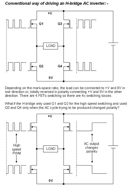
The top diagram is as I normally read about inverter designs but the lower diagram struck me as a means of cutting switching losses by virtually 2.
I've never seen it before so I thought I'd aske here if anyone else had - maybe there's a "problem" that I don't recognize. Anyway, I decided not to enter the competition if anybody wonders why I'm posting this.
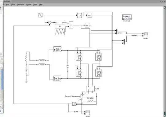
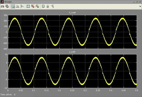
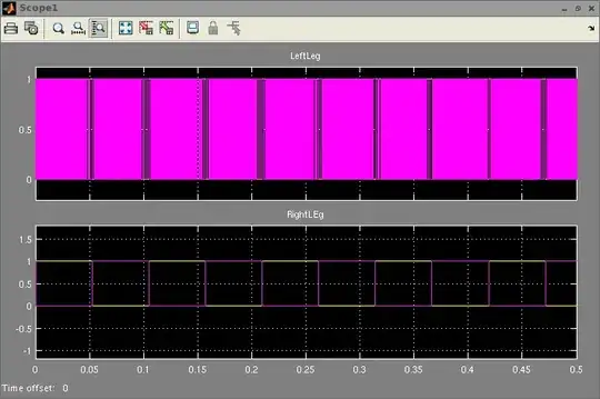
EDIT - just to explain how I think it should work - Q1 and Q2 (using PWM) can generate (after filtering) a "smoothed" voltage that can vary between 0V and +V. To produce the first half cycle of a power AC waveform, Q4 turns on (Q3 off) and Q1/Q2 produced the PWM switching waveforms to make a sinewave from 0degrees to 180. For the 2nd half cycle, Q3 turns on (Q4 off) and Q1/Q2 produces an inverted sinewave voltage using the appropriate PWM timings.
Question:
- Is there a problem that I'm unaware of in this type of design - maybe EMC emissions or "it just won't work stupid!"