11

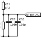
I have recently taken on a project that involves improving a circuit and there is a couple of instances where there are two capacitors in parallel with each other.

The values of these capacitors are 100nF and 100pF so one is average sized while the other is small. The instances of these capacitors in parallel are placed on input/output signals, one on an output that is readings a battery voltage and the other on a power input to an op-amp. I am a bit confused as to why they are both needed as opposed to one so if anyone can point me in the right direction with regards to that, that would be great.

Picture of parallel caps

MrPhooky
  • 2,168
  • 8
  • 24
  • 55
  • 1
    Is the 100n capacitor electrolytic and the smaller one ceramic? – nav Sep 19 '14 at 08:44
  • 1
    I've seen that on power inputs to MCUs, where the 100nF is the standard decoupling capacitor (feeding power on MCU internals switching), and the 100pF is filtering high-frequency transients. – gbulmer Sep 19 '14 at 08:50
  • 1
    Could be to filter out transient noise at different frequencies where each cap, best performs for a particular band ? Could also be used for as a power reservoir where each where the lower cap responds faster to the demand ? – efox29 Sep 19 '14 at 08:50
  • 1
    @nav I believe that they are both ceramic – MrPhooky Sep 19 '14 at 08:53
  • 1
    Several nice answers. I'll guess for this battery/opamp application you could snip out the 100pF with out changing much... Does the opamp really care about a little more 0.1-1 GHz noise? But this won't improve it. (And who knows it may be needed.) – George Herold Sep 19 '14 at 14:19
  • 1
    You can not answer for sure, if the physical positions of the capacitor is anknown – GR Tech Sep 20 '14 at 05:55

3 Answers3

18

Capacitors eventually stop behaving like capacitors at high frequencies and exhibit resistive and inductive effects. The 100pF capacitor filters high frequencies that the 100nF capacitor could not.

This is shown clearly on the diagram below which shows the impedance (Red) of a 100nF capacitor and a 100pF capacitor (Light Grey top curve) versus Frequency. See how the 100nF capacitor starts to look inductive from about 10MHz whereas the 100pF is still capacitive out to 1GHz.

enter image description here

Link to the Kemet Spice Tool used for the capacitor analysis.

akellyirl
  • 4,117
  • 1
  • 16
  • 30
11

Basically, any capacitor has a little bit of series inductance. This makes it series resonate at some fairly high frequency and up to that frequency the capacitor behaves like you would expect but, higher than that frequency, the capacitor's impedance rises like an inductor ie it no longer behaves like a decent decoupler.

For a 100pF cap this happens at a much higher frequency than the 100n cap so, the joint effect from both caps yields the "bulk" capacitance of the 100n with the ability to remain capacitive at much higher frequencies.

enter image description here

The picture above also shows the effects of PCB track lengths - clearly a track has inductance somewhat proportional to length and this adds to the internal parasitic inductance of the capacitor making it resonate at a lower frequency. Also shown are "ideal" capacitor responses (no series inductance).

Andy aka
  • 434,556
  • 28
  • 351
  • 777
5

I've seen a similar scheme on power inputs to MCUs, especially for ADC sections.

where the 100nF is the standard decoupling capacitor (feeding power from the capacitor to supply the MCU internal circuit), and the 100pF is filtering high-frequency transients.

ST use a similar scheme for STM32F103

In Figure 14 on page 36, the use 1uF + 10nF for the power supply for the ADC.

Application note AN2834 "How to get the best ADC accuracy in STM32Fx Series and STM32L1 Series devices", explains in section 3.2.1 "Reference voltage/Power supply noise minimization" the rational for the 0.1uF + 10uF:

It is recommended to connect capacitors with good high-frequency characteristics between the power and ground lines. That is, a 0.1 μF and a 1 to 10 μF capacitor should be placed close to the power source. The capacitors allow the AC signals to pass through them. The small-value capacitors filter high-frequency noise and the high-value capacitors filter low-frequency noise.

gbulmer
  • 10,040
  • 20
  • 29