3

I am designing a pressure calibrator (my first Real project), which is supposed to measure from 0-200.00 mmWC (20000 counts) using Silabs C8051F350 (inbuilt 24-bit Sigma delta ADC). Sensor used is a typical Wheatstone bridge type Differential Pressure sensor.

This is the schematic to generate Bridge voltage (Vbridge) for the sensor. ADC-Vref seems to very be noisy on DSO (few mVp-p).

Vbridge voltage is derived from ADC Vref

In almost all our instruments, previous Engineers have freely used AD620 to condition differential pressure signal, however cost of that INA has now increased too much for us to throw it randomly in our circuit so we have resorted to following arrangement. Common mode rejection to be dependent on ADC's PGA's CMRR, which is stated to be typical 100 dB at 50/60Hz BW.

schematic

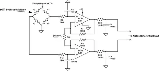
simulate this circuit – Schematic created using CircuitLab

So here's my first question: Is this ADC driver, Vbridge generation a viable method. I mean is it going to give me good, less error, less noisy performance (because my step size with a 5mV full span sensor would be 0.25uV/step).

Sorry for using words like good and less, I can't speak actual number since noise voltage calculations and stuffs are above my head.

And my main concern is: We are deriving 5V from a single cell Li-ion and Boost converter(MCP1640) which also has few mVpp of ripple.

So is it an intelligent idea to use such a switching power supply in Analog sensitive instrument.

JYelton
  • 32,302
  • 33
  • 134
  • 249
Sajid
  • 483
  • 1
  • 6
  • 20

3 Answers3

1

I will address the "Main concern" directly - should you be using a switching supply to power analog sensitive instruments?

No.

It is low power i'm assuming, so find a 2-cell LiPo battery and go straight for a linear regulator (LDO) with ultra-low noise and filter capacitor support such as the MIC5323 which states in the datasheet very low (20 uV rms) ripple.

If you have higher power and less sensitive components, go ahead and use a DC-DC switching converter for those areas of your circuit.

Of course, you could try to do some serious filtering and testing on perfecting the output and quality of your switching supply.

It is far easier though to use a linear regulator supply specially for the ADC related circuitry, and keep the power and ground loops from the regulator dedicated only for this area, and connect the ground of the LDO to the system ground somewhere else, perhaps even decoupled with ferrite beads and whatnot.

KyranF
  • 6,248
  • 16
  • 25
  • Yes, My adc is powered with 3.3V from a LDO. I need 5V for my LCD and Vbridge. Should I power my LDO with boost converter or direct Li-ion? – Sajid Sep 19 '14 at 09:33
  • @Sajid direct from Li-ion, just make sure your battery doesn't get below 3.3+drop out, if you were not careful about referencing the 3.3V rail as analog reference. You should always use a precision reference like 3V or similar, from a 3.3V supply just for that reason. Do you have a precision shunt reference or something like this? – KyranF Sep 19 '14 at 09:55
  • No Kyran, good quality Reference will increase the cost of the instrument. So we are trying to manage without reference. – Sajid Sep 21 '14 at 16:24
  • okay, @Sajid as someone else mentioned if you do not need absolute reference, rather a ratiometric reference is okay, then do what they said in terms of the input supply/ADC reference to reduce noise.. – KyranF Sep 21 '14 at 17:48
1

I'd suggest a slightly 'radical' approach... Connect your bridge directly to your battery, and then connect your ADC's Vref INPUT directly to the battery too.

Before you dismiss this idea, think about it a bit. The output from your bridge is ratiometric - in other words, it is proportional to its supply voltage. The converted result from your ADC is also proportional to the Vref you give it, but inversely.

So on the one hand, a higher voltage into the bridge will produce a larger signal out, but a larger Vref on the ADC will counteract that by producing a smaller result.

I have used this idea a number of times in load-cell & strain-gauge applications with great success.

brhans
  • 14,373
  • 3
  • 34
  • 49
  • Exactly sir, that's the whole idea of "Generating" Vbridge. We are using inbuilt Vref of F350 which is around 2.43 V and Vbridge is dependent on Vref which takes care of inaccuracies of Vref. One more question by the way, will it be better from SNR perspective if I connect 3.3 V of LDO directly to Vbridge and Vref and amplify my bridge output to fit in the ADC range. I can't connect them directly to battery since ADC Vcc is 3.3V and battery V can be 4.2 V. – Sajid Sep 21 '14 at 16:16
1

The OP-AMP proposed is a MCP6V07 with an input noise density of around 60 nV / \$\sqrt{Hz}\$ - I've kind of averaged this in my head across the range that your circuit seems to work i.e. DC to about 16kHz. It's 16kHz because of the 100 ohm and 100nF low pass filter on the output of each op-amp.

What noise does this mean in reality? Well, other people cleverer than me have said that if the filter is a simple single order low pass filter then you better consider 1.6x the cut-off frequency for the true effects of noise so, that's a bandwidth of about 25kHz - now take the square root and you get 158. Multiply that by 60nV and the equivalent input noise due only to one op-amp is about 10 microvolts RMS. There are two op-amps each with the same noise and these noise will add to give 3dB more noise i.e. about 14 microvolts RMS into your ADC if the gain of the Op-amp circuit were unity.

Compare this with an AD620 - it has two quoted figures; input noise and output noise. Input noise is 9 nV/\$\sqrt{Hz}\$ and output noise is 72 nV/\$\sqrt{Hz}\$ so immediately there is a benefit to using the MCP6V07 but waiiiiiit....

.... Will the circuit gain be unity or is it more likely to be ten? If it's a gain of ten then the INA wins hands down because its output noise remains at 72 and is added vectorially to its input noise x10 - this would be a figure of \$\sqrt{90^2+72^2}\$ nV/\$\sqrt{Hz}\$ = 115 nV/\$\sqrt{Hz}\$.

The op-amp (on the other hand) would be a lousy \$10\cdot\sqrt{60^2+60^2}\$ nV/\$\sqrt{Hz}\$ = 848 nV/\$\sqrt{Hz}\$.

These last two figures are output noises of course because I've multiplied them by my assumed gain of ten. If the gain is different then you now, hopefully, have the math to work it out. If you could decide on what circuit and gain value then you are in business - I've just compared devices.

Back to assuming a gain of unity and the op-amp circuit - 14 microvolts of noise into your ADC - talking of which, I opened the data sheet on the C8051F350 but it appears to be longer than the koran and bible back to back so, given that you have an anti alias filter of about 16kHz which pretty much excludes noise above 25kHz (say) I am willing (but not overly excited) about making the assumption you are sampling at 50kHz - if it's a lot less than this then sort out the 100 ohm and 100nF and make them more reasonable.

Assuming that you will measure the full 14 microvolts of noise and that your FSD input is (say) 2.5 volts, you can make a rough estimate of signal-to-noise ratio. The sinewave needed to generate a FSD of 2.5 Vp-p is 0.88V RMS.

This means your SNR is a measly 96 dB - yet you are using a 24 bit device. 96dB is about an ENOB is 16 bits (rough, head calculation)

If you want close to 20 bits ENOB you are going to have to vastly improve the interface circuit.

Andy aka
  • 434,556
  • 28
  • 351
  • 777
  • Really very informative answer sir, I've taken a printout of your answer and will attach it in the project file. Some more questions have come to my mind. My signal is just a DC mV from wheatstone.(I will have to use some external gain since PGA is limited to 128) What will be the bandwidth in my case? ADC is set at sampling rate of around 19.2Khz since they stated it as optimum sampling rate in datasheet. Also shouldn't I expect my ADC's PGA's CMR to reject common mode noise from both the amps. I only need 16 bit accuracy, so what will you suggest for that? – Sajid Sep 22 '14 at 11:04
  • The noise from both amps is of the same RMS value but as noise signals they are incoherent therefore no, it will not be rejected. My advise, for driving any ADC is make the filter on each op-amp output pass only the frequencies you need. If sampling at 19.2kHz then the filter is already letting too many frequencies thru and this generates excess noise. If you only need a 3dB bandwidth of (say) 1kHz then make the RC filters have a 3dB point of 1kHz. – Andy aka Sep 22 '14 at 11:35