3

I want to build an H-bridge to control a 36V dc motor (or possibly 48V but lets stick to 36V for now)

The electronics that will control the H-Bridge (logic, etc) will run from a 12V very-small-like-really-really-low-current source, and I have a bit of a problem regarding the driving of the low-side (switching) mosfets.

I obviously can't run them on my 12V power supply, so I have to use the 36V supply which of course is too much for my mosfets! (maximum Vgs is about 20 volts or so)

What I have come up with is this:

Sample of my idea

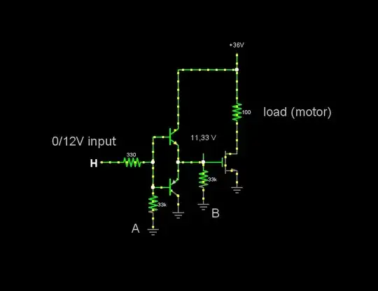
I want to know if such an idea will work, and if that's the case, which of the two pull-down resistors you would prefer? (A or B)

I know that adding the B resistor will cause the upper (NPN) transistor to always be in forward active mode and thus always dissipate power, whereas by adding the A resistor the upper transistor will be in cutoff once the gate capacitance of the mosfet will be fully charged.

For some reason I would feel better if the pull-down was attached directly to the mosfet but maybe I am just paranoid...

Konstantinos
  • 31
  • 1
  • 2
  • 1
    Please ignore the values of the components, that is not what this is about.. I don't really know yet what values I will choose so just focus on topology-related issues rather than numbers! – Konstantinos Sep 18 '14 at 18:35
  • 2
    Why can't you use 12V to switch on the low-side FET? – Dan Laks Sep 18 '14 at 18:37
  • Not enough juice (power) to turn the mosfets on as fast as I would like. If that were the case, don't you think I have wasted your as well as my time creating this question? :P – Konstantinos Sep 18 '14 at 18:47
  • Is H connected to a push-pull output? – Ignacio Vazquez-Abrams Sep 18 '14 at 18:48
  • Also, are you certain about the bipolars, i.e. NPN vs. PNP? – Ignacio Vazquez-Abrams Sep 18 '14 at 18:49
  • Yes of course its a 12V sink/source.. What's wrong with the bipolars? The upper one is NPN and the bottom is PNP.. – Konstantinos Sep 18 '14 at 18:59
  • 1
    Looks OKish - but while you need good current at turn on/of it's low otherwise so not a vast load on 12V as long as filtercaps are ok. Calculate 0.5 C V^2 f to get mean power. The two transistor driver pair works well. Consider a small series gate drive resistor (helps stop ringing). Add a reverse bias zener on FET g to s as close to FET as possible Vz > Vgate_drive, that its days may be long ... . Helps heaps. – Russell McMahon Sep 19 '14 at 00:01
  • I'll try to increase my 12V filter caps and see what that leads me, thanks for your input! – Konstantinos Sep 19 '14 at 11:32

2 Answers2

1

What if you dispense with the buffer transistors and add some capacitance to your 12V rail?

The continuous current rating will remain the same, but a few uF should prop it up for the brief surges required to charge the gates.

There's also the output current rating of your logic to consider, mostly the peak rating.

AaronD
  • 5,596
  • 10
  • 36
  • Well I will give that a try.. Do these capacitors have to be of a specific type? I think I've read that ceramics are better for higher current surges but I am not 100% sure about this – Konstantinos Sep 19 '14 at 11:31
  • Yes, but they tend to be expensive for larger sizes. Most serious designs end up with two or more in parallel: a relatively large electrolytic and one or more smaller ceramics in different sizes. This is because capacitors only work below a certain frequency; smaller caps are also "faster", so a high-speed digital design may need 4 or more just to keep up. For you though, I'd suggest a 10-100uF electro and maybe a 0.1-1.0uF ceramic. That's my standard configuration before I test it, and most of the time, it doesn't change. – AaronD Sep 19 '14 at 13:59
  • More details about parallel caps here: http://electronics.stackexchange.com/questions/129888/parallel-capacitor-conundrum – AaronD Sep 19 '14 at 18:45
0

Neither A nor B are needed - the PNP transistor will pull down the gate to about 0.7 volts when the input to the BJT push-pull circuit is at 0V and this is neither aided nor hindered by either resistor. What I will say is that the MOSFET shown in your circuit may not get adequately turned off and this could be a problem. This is because the PNP is an emitter follower and the emitter won't get lower than about 0.7V.

Another problem is when turning on the MOSFET - if (H) is logic fed it'll only be 5V and the max voltage seen on the gate would be somewhat less ~4.3 volts, again due to the NPN acting like an emitter follower. If your logic drive is 12 volts then there's less of a problem.

I'd use a proper MOSFET driver circuit like those on offer from various suppliers like Fairchild and Linear technology

I would also think that the actual real power needed to drive this MOSFET isn't going to be that great and probably less than 100m watts so, maybe, the 12 volt supply you have, might just be conscripted into action. If not I'd consider a buck regulator to drop the 36V to 12 volts.

Andy aka
  • 434,556
  • 28
  • 351
  • 777
  • I am aware of the Vbe drop regarding the BJT's but as it is the logic drive is 0/12V as stated so no problem there.. Maybe adding that B resistor would be a good idea after all, in order to get rid of that .7 of a volt that would keep my mosfet from completely turning off? On a side note, if you do you know of any MOSFET drivers that accept 36V (or 48V just in case) as "rail" voltage, please do tell! – Konstantinos Sep 18 '14 at 21:00
  • You said (virtually) "the electronics that will control the H-Bridge (logic, etc) will run from 12V" and didn't explicity say the logic levels were also 12 volt and it's best not to assume. B might help turn it off but it all depends on switching frequency and gate capacitance of the MOSFET. If B doesn't discharge Cgate much then no, it won't help. – Andy aka Sep 18 '14 at 21:05
  • @Andyaka is right: if you want to turn it off quickly (and I presume you do), then the extra resistor is not going to help unless it's so strong that you don't really need the transistor. A weaker one will have done its job well before you can get a meter on it, but at higher frequencies, the FET will get hotter because it's spending more time not completely off. – AaronD Sep 18 '14 at 21:31