6

Background: I need to wirelessly charge a battery at about 100W. However, there seems to be a gap in the wireless charging market. There are plenty of wireless power transfer systems operating in the sub 20W range for mobile phones, and several in the multi kW range for charging cars. But nothing I can find in the 100W range.

So I'm thinking of designing my own. Before I go too far, I'd like to sanity check my idea to make sure it will fit within the size and weight constraints of my system.

Question: Is there some way to estimate the size and/or weight of the coils required to wirelessly transmit power; some equation or rule of thumb?

Added: I haven't thought about the frequency yet, as I'm still trying to determine if this is feasible. So far, I can't find much information about sizing coils. However, I've just realised that I'll be able to have the ferrites of the coils touching, so this should improve efficiency.

Rocketmagnet
  • 26,933
  • 17
  • 92
  • 177

4 Answers4

9

An alternating current through a transmit coil induces an alternating voltage in a receive coil. The receive coil in a regular transformer is called the secondary winding and this receives about 97% of the magnetic flux produced by the transmit coil (primary) so, this sets the basic scene.

What you need to design is a transformer with a small airgap. Using ferrites is a good idea because then you can make the airgap shorter and actually direct the alternating magnetic flux to where it has to go - the higher the percentage flux received thtough the secondary, the more power you can effectively transmit to a receiving load.

However, when you have a situation where the flux coupled is a much smaller fraction (say 50%) you have to start to do tricks and one of those is operating the coils at several kHz to a hundred kHz and tuning the coils (they are inductors after all) with capacitors so that they resonate. What happens when the transmit coil resonates - you get current amplification into the coil and this boosts the magnetic flux and more flux is received (it may still be 50% coupled but, for a given stimulus of current to the primary tuned circuit, there can be double or more current in that actual coil).

This brings me to point out one of the things that you need to be wary of - if you have a highly tuned primary, off-load i.e. not interfacing with the load on the secondary, the terminal voltage of the transmit coil can create massive currents and bang, you coil fries. You have to have a mechanism that limits the current in the transmit coil and this can be a little sophisticated.

In a regular transformer, if a current is taken from the secondary this is reflected by a current in the primary that, in-effect, "forces" the secondary voltage to largely remain regulated. Not so when coupling is low.

You could short out the secondary/ recieve winding and you'll just find that the transmit winding current rises but doesn't go crazy like a regular transformer - this again is due to lack of 100% coupling and ultimately defines how much power can be transferred at a given distance and coil topology.

If you need the maths, here's a picture that can help: -

enter image description here

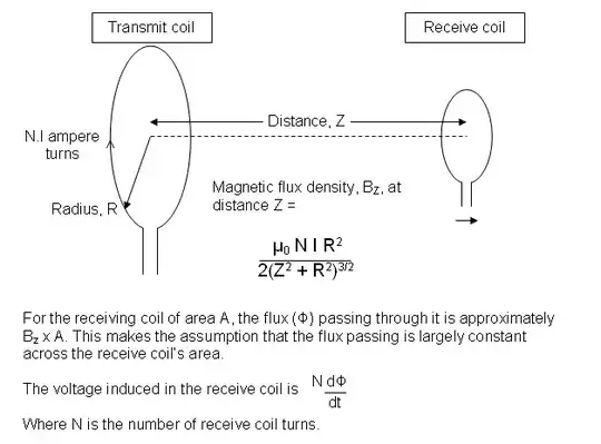
The above picture is for coils totally in air - clearly if you use ferrites to minimize the gap the flux received formula effectively reduces the Z dimension and, as the coils get very close (and the same diameter) you have a regular transformer. It's also worth noting that tuning the receive coil with a capacitor is also going to mean you can get more current out - I know it doesn't look this way but the receive coil with a physically parallel capacitor is in fact a series tuned circuit due to the way voltage is induced in series with the receive coil - when this happens the leakage inductance of the secondary/receive coil is totally cancelled out meaning the output impedance of the coil is only limited by the coils internal resistance.

Good luck and, if you get a chance let us know how you get on with your design. Part of my job is powering rotating electronics (stuff on jet engines used to collect data) and we have to throw a couple of watts across a sometimes sizable gap of up to 40mm with usually non-ideal coils so I have a personal interest.

Andy aka
  • 434,556
  • 28
  • 351
  • 777
  • Thanks, there is a lot of useful stuff in this answer, although nothing about how big my coils might be. The more I think about it, the more I think I just need to make an isolated DCDC power supply, but make the transformer separable. Linear have a couple of good chips for this. – Rocketmagnet Sep 18 '14 at 22:51
  • 1
    R = radius which implies coil size and I also pointed out that making the receive coil the same diameter as the transmit coil will maximize flux coupling too. You are forgiven for missing this because there's a lot to take in LOL. – Andy aka Sep 18 '14 at 22:54
3

You can think of it as designing a transformer, and the same principles apply. At higher frequencies the transformer size can be smaller (but core losses increase and skin effect forces you into Litz wire).

Smaller gap means lower leakage inductance, though even if the ferrites are touching you should not assume zero gap, maybe a couple thousandths of an inch. Getting 100W through something the size of a roll of sticky tape should not be too difficult.

Spehro Pefhany
  • 376,485
  • 21
  • 320
  • 842
2
  1. Determine the max worst case spacing between Tx and Rx coil. Based on it, try making both the ID's of coils twice that distance or more.
  2. Determine the method which will be used for power transfer control, will it be via frequency changing between 110 kHz to 205 kHz or will it be fixed frequency with burst pulse duration.
  3. Then determine what voltage you are working with on Tx and expecting on Rx. Based on it balance the Tx coil inductance such that at full load current the max current that you would like going through the coil is acceptable to the wire gauge selected.
  4. Get a resonant cap tuned to the coils on both sides. 100 kHz for frequency change type, else resonant to the fixed freq if going that route.

Notes:

  • Impedance of inductor, L = 2 * pi * Freq * L ohms
  • Impedance of cap, C = 1 / (2 * pi * Freq * C) ohms
  • Total circuit impedance = DC resistance of coil wire + (impedance of L - Impedance of C)

Calculate the above values at multiple points of frequency operation.

For a given Vinput, current through coil = V / total circuit impedance. This helps you select the coil wire thickness or reciprocally you increase inductor L till current is reduced to safe limit.

Thats all to it. Just make it and play around with it till you like something that works for you.

Transistor
  • 168,990
  • 12
  • 186
  • 385
Samuel. C
  • 21
  • 1
1

Several people have done a bunch of demos of 60 W wireless power transfer (lighting up a 60 W lightbulb to full brightness): People associated with MIT, Intel, and Witricity;(a) (b) (c) (d) People associated with Yale and FREE-D have done similar demos;(e) Various other demos.(f)

Because of reciprocity, an antenna designed to transmit a certain amount of power can (theoretically) receive the same amount of power at the same frequency. You may find it useful to look at induction heating coils in your desired power range and their drive circuits; theoretically a similar coil could could be used to receive the power it transmits and convert back to electrical power.

(This comment was a little to long to fit in the "comment" box, so I'm posting it as an "answer", although I hope other people post better answers).

davidcary
  • 17,426
  • 11
  • 66
  • 115