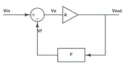
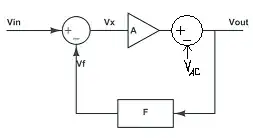
When the input goes positive, the output of the op-amp is a large
positive signal which turns on the diode and completes the feedback
path.
That's not quite true. As I show below, assuming the diode obeys the diode equation, there is no 'completing the feedback path' to speak of as there is a well defined feedback voltage function for any input voltage as long as the op-amp isn't clipped.
What I don't understand is what happens to the initial output of the
op-amp which was the signal multiplied by the large gain A
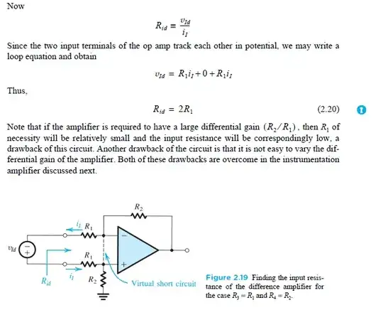
The output of the op-amp is some very large number \$A\$ times the difference of the non-inverting and inverting input terminal voltages. In this circuit, the non-inverting input voltage is just the source voltage.
The inverting input voltage is just the output voltage \$v_{OUT}\$ and is given by
$$v_- = i_D \cdot R_L = v_{OUT}$$
where
$$i_D = I_S \left( e^{\frac{v_O - v_-}{nV_T}} - 1\right)$$
and the op-amp output voltage \$v_O\$ is
$$v_O = A(v_+ - v_-)$$
thus
$$v_- = I_S \left( e^{\frac{Av_+-(1+A)v_-}{nV_T}} - 1 \right)\cdot R_L = v_{OUT}$$
After substituting \$v_{OUT} = v_-\$ and \$v_+ = v_{IN}\$ and some algebra, we have
$$v_{OUT} + \frac{nV_T\ln\left( \frac{v_{OUT}}{I_SR_L}+ 1\right)}{1+A} = \frac{A}{1+A}v_{IN}$$
Recalling that
$$v_O = A(v_+ - v_-) = A(v_{IN} - v_{OUT}) $$
see that, for every value of the input voltage \$v_{IN}\$, there is an output voltage that satisfies the above equation and thus, an associated op-amp output voltage (until the op-amp 'clips') so this is the answer to your question. This can be verified with a circuit simulator.
Note that, due to the logarithmic term
$$v_{OUT} \approx \frac{A}{1 + A}v_{IN}\;,\quad v_{IN} > 0$$
and
$$v_{OUT} \approx 0\;, \quad v_{IN} < 0 $$
as expected.