3

I need to use the magnetometer in a device to accurately determine how many degrees the user twists (rotates in x-y plane) it. I don't care about absolute orientation, just the angular delta. Of course the user can hold the device in any orientation. Essentially, this is like a doorknob that isn't attached to anything.

I tried atan2(x, y) but the resulting anglular delta varies depending on the device's orientation. Some research suggests that tilt compensation is needed, but all solutions are for correcting compasses based on knowing the gravity vector.

In this application, accelerometer, gravity, gyro data are not available -- just the magnetometer. This means that the pitch & roll used in typical solutions aren't available. However, I'm not looking for true headings, just rotation in x-y.

Can anybody explain the math & solution for this? I realize this is strictly speaking a programming question, but this is stuff that only an EE would know.

The application is typically used such that the x-y plane is rarely, if ever, perpendicular to the earth's field, so sqrt(x2+y2) > 0.

The magnetometer is an AK8975 3-axis MEMS soldered to the device with no gimbal-type leveling arrangement. Hard-iron calibration is already taken care of. Sampling rate is 40 Hz whereas the fastest you can twist your hand back & forth is less than 5 Hz. The magnetometer's orientation is totally unknown since the magnetometer's axis is fixed to the device and the device can be in any orientation. Nothing is known or can be assumed about gravity nor the device's orientation or location.


[Later] Did an experiment where I took the device and lay it flat on a swivel chair facing North, then rotated it thru 360. The chair seat is level with the ground. Here's the chart: x=blue, y=dark green, z=red, sqrt(x^2+y^2+z^2)=aqua
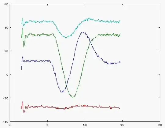
x=blue, y=dark green, z=red, sqrt(x^2+y^2+z^2)=aqua The x-axis is elapsed seconds, y-axis is uT.

Two things jump out at me:

  1. Shouldn't the aqua-colored magnitude be flat? The trough is 30 vs. 45 for the flat part. Otherwise, is this a tipoff that this sensor is grossly mis-calibrated? Or is this an indication that tilt compensation is needed?
  2. The x & Y peaks are slightly offset and have slightly different ranges, but not by that much. This, I'm willing to shrug off as error, as opposed to the 30:45 difference for the magnitude which seems sufficient to mess up any calculations.
  3. The Z is flat as expected
MilesK
  • 51
  • 7
  • 2
    What if the vector of magnetic intensity points in the direction of z-axis? – venny Sep 16 '14 at 19:40
  • 1
    What kind of magnetometer? A two axis flux gate? Is the orientation of the z axis fixed? (assumed parallel to the earth's g-field) Do you know the magnetic field vector where you are? Which direction does it point? Will it be used inside a building? – George Herold Sep 16 '14 at 19:44
  • +1 to GeorgeHerold. Also, can the magnetometer be sampled at a *much* higher rate than it will move, i.e. many times higher than the [Nyquist rate](http://en.wikipedia.org/wiki/Nyquist_rate). How slowly might you need to detect? (I'm wondering about drift). What constraint, if any, might you be able to relax or remove if the answer is "it can't be done". – gbulmer Sep 16 '14 at 20:25
  • Please see edits at bottom of question for the answers to the points you raise. – MilesK Sep 16 '14 at 20:26
  • 1
    It is impossible because rotation along magnetic field vector is undetectable. – venny Sep 16 '14 at 20:53
  • @venny as stated in the edits of the question, the application is not used in situations where the rotation is along the magnetic field vector, so that case isn't a problem. As I have measured, rotation in all other cases is detectable, but I'm trying to find how to tilt-compensate it. – MilesK Sep 16 '14 at 21:11
  • So correct me if I'm wrong, but contrary to the title of your question, I'm understanding that you *don't* want tilt compensation; rather, you want to know if the device has rotated in *its own* X-Y plane, using the prevailing magnetic field for reference, right? As venny points out, it can't be done if the Z axis is parallel to the field, but as long as the field vector has a nonzero projection in the X-Y plane, I don't see a problem with measuring its angular changes. Where exactly are you getting stuck? – Dave Tweed Sep 16 '14 at 21:14
  • @DaveTweed You're exactly right. I'm trying to compute the difference between two angles in the device's own X-Y plane caused by the user twisting the device like a doorknob. The angles are trivially derived from the x & y projections using atan2, e.g. dAngle = atan(x1,y1) - atan(x1,y2). The problem I'm seeing is that dAngle is different if the user twists by the same amount while holding the device vertical vs. horizontal, or facing east vs. north. This is why I said tilt compensation in the title: this seems to be the same problem but cast a different way, with different constraints. – MilesK Sep 16 '14 at 21:28
  • It will differ depending on the orientation, if the x-y plane is perpendicular to the Earth's field, then no changes will be registered, if parallel to the field then you will see the most change. – copper.hat Sep 16 '14 at 21:35
  • How much is dAngle different? And what kind of accuracy/repeatability are you looking for? You may simply be running into the resolution limits of the 13-bit sensor (0.3 uT/count). Try plotting some of the raw sensor data, and working through the arithmetic to verify. – Dave Tweed Sep 16 '14 at 21:39
  • @DaveTweed: If the device is held with the x-y plane perpendicular to the Earth's B field, then only a z component (modulo noise) will register. So it cannot detect any rotation around the z direction (in this case). Just like if I am at Magnetic North, an ordinary compass will be of no use for direction finding. – copper.hat Sep 16 '14 at 21:45
  • 1
    Quantisation error is the last thing I would be afraid of. But zero-gauss offset is \$\pm 1000\,\mathrm{LSB}\$ and sensitivity may vary by \$\pm 5\,\mathrm{\%}\$. And if you want to ensure that projection into XY is non-zero, you are restricting yourself to horizontal position. – venny Sep 16 '14 at 21:47
  • @Copper.hat I'm working on more data right now, per DaveTweed's suggestions – MilesK Sep 16 '14 at 21:54
  • @copper.hat: YES, WE GET IT! You don't need to keep saying that over and over again! The device can still be useful in other orientations. – Dave Tweed Sep 16 '14 at 21:54
  • @copper.hat: I think we're talking at cross-purposes here. The goal is to determine how much the device has rotated in its own X-Y plane, assuming that the direction of the external magnetic field is fixed. This should be quite doable. Why would the rate of change of the angle be underestimated by any amount? – Dave Tweed Sep 16 '14 at 22:09
  • @Venny has a good point about sensor offset errors, however. What sort of calibration procedure are you using to eliminate these? – Dave Tweed Sep 16 '14 at 22:11
  • @copper.hat: You're not thinking this through. As long as anything shows in the X-Y plane, measuring the angle of its rotation should be doable, within the resolution limits that I pointed out earlier. The *magnitude* of the projection DOES NOT MATTER (unless it's zero, of course). – Dave Tweed Sep 16 '14 at 22:25
  • Check out the graph I just added to the question and the comments afterward. Ring any bells? – MilesK Sep 16 '14 at 23:04
  • Y axis is in gausses and X axis in radians? – venny Sep 16 '14 at 23:30
  • @venny X-axis is elapsed seconds, y-axis is uT. Rotation starts @ ~5 sec, ends @ ~12 – MilesK Sep 16 '14 at 23:44
  • It is sinusoid, shifted by 90 degrees from *y*. The difference in amplitude may be caused by imperfect alignment of z-axis with the chair axis. But also there is some serious offset which is real and has to be calibrated. – venny Sep 16 '14 at 23:50
  • @venny Chair is mainly aluminum & plastic. The y *is* the same sine curve as z, just offset 90 degrees by as you'd expect. – MilesK Sep 16 '14 at 23:53
  • @copper.hat It does. Draw a box between 5s and 12s, copy it several times and you will see two shifted sinusoids. – venny Sep 17 '14 at 00:06
  • Nobody's commenting about that bump in the magnitude (aqua)! Why wouldn't this be a straight line? – MilesK Sep 17 '14 at 00:08
  • With ideal sensor, it would be flat. This sensor has guaranteed initial accuracy of \$\pm 300\,\mathrm{\mu T}\$, so these results are actually pretty good. – venny Sep 17 '14 at 00:12
  • @venny: Of course, silly me. – copper.hat Sep 17 '14 at 00:14
  • @MilesK: Based on what you have, try figuring out a min/max of x,y separately, then normalise each separately and then\ take the magnitude. I think you just have mismatched \$x,y\$ ranges (and zeros). – copper.hat Sep 17 '14 at 00:17
  • @venny Could you amplify on your comment about "initial accuracy of 300 uT"? Is this an offset, non-linearity, or what? Also, could that be a misprint? 300 uT for a sensor with 0.3 uT LSB accuracy seems fishy. – MilesK Sep 17 '14 at 00:18
  • @MilesK It is zero-gauss offset. See it for yourself in [datasheet](http://www.akm.com/akm/en/file/datasheet/AK8975.pdf), page 8. I do not think it is a misprint, similar sensor from ST has typical offset of \$\pm 100\,\mathrm{\mu T}\$ – venny Sep 17 '14 at 00:35
  • @venny I see. How does the constant offset produce a bump in the curve? What am I missing? – MilesK Sep 17 '14 at 00:50
  • @MilesK Each axis probably has different offset, and even if all had the same, the result would not be flat because \$\sqrt{x^2+y^2+z^2}\$ is not a linear combination of x,y,z. The dip is centered at the blue line minimum which is not low enough. – venny Sep 17 '14 at 01:17
  • @venny Of course! So it looks like I'm looking at bad hard-iron calibration as my root cause. – MilesK Sep 17 '14 at 01:35
  • Take a look at this [application note](http://www.freescale.com/files/sensors/doc/app_note/AN4246.pdf) from Freescale, especially the figure on page 11 which shows that uncalibrated values can be way off. Calibration by rotating in all axes (like with a mobile phone) is probably necessary. – venny Sep 17 '14 at 01:56
  • @MilesK: I have calibrated accelerometers which have similar issues. I measured lots of points and used a SVD technique to fit them to a sphere from which I extracted means and ranges. I would do something like that first. – copper.hat Sep 17 '14 at 02:03
  • @MilesK: Excuse my catching up here, but are you saying that the user **only** rotates in the x-y plane of the device? That is, is the orientation of the z axis **fixed** for the measurement? – copper.hat Sep 17 '14 at 05:04
  • @copper.hat Yup, z is fixed for the duration. – MilesK Sep 17 '14 at 18:18
  • Guys, I wish I had enough reputation to upvote some of your comments. Using the 4-parameter calibration described in the Freescale application note linked by @venny, I was able to recalibrate the magnetometer to get flat-line magnitude. THAT CHANGED EVERYTHING for the better. – MilesK Sep 17 '14 at 18:18
  • I stand corrected... – copper.hat Sep 17 '14 at 18:25
  • With proper calibration, I did some tests where I rotated the device thru 360 degrees in X-Y. In all orientations, the chart of x vs. y is now perfectly round. This proves empirically that me that DaveTweed is perfectly correct: the angle of rotation is simply atan2(x, y). – MilesK Sep 17 '14 at 18:34

2 Answers2

1

If the orientation of the device is fixed during the measurement then the computation is relatively straightforward as Dave Tweed has pointed out.

The main issue is calibration. A quick way would to establish at an approximate min, max for each x,y,z direction. Hopefully the zeros will lie roughly on the averages of the min and max. That is, this will give an \$x_\min\$, \$x_\max\$ and similarly for the other axes. From this estimate \$x_\text{zero} = {1 \over 2} (x_\min+x_\max)\$, and \$r_x = {1 \over 2} (x_\max-x_\min)\$, etc.

Then for a reading, compute \$x_\text{est} = { x_\text{meas}-x_\text{zero} \over r_x} \$, etc. Hopefully this will be in the range \$\pm 1\$.

I would check that \$|z_\text{est}|\$ is (1) no larger than some number (\$<1\$ here) so that you get a meaningful direction, and (2) that it remains fairly constant for the duration of a measurement.

To compute an angle, use \$\text{atan2}(y_\text{est} , x_\text{est})\$ (check your particular API). To compute the difference with another (hopefully nearby) angle, just be careful with the \$\pm\pi\$ boundary.

This is obviously a quick overview with many optimisations and sanity checks omitted.

copper.hat
  • 837
  • 7
  • 16
  • As an aside: The following discusses the mathematics behind one class of approaches to calibration http://www.ulb.ac.be/assoc/bms/Bulletin/sup962/gander.pdf. – copper.hat Sep 17 '14 at 14:45
  • As referenced by venny, Freescale's [application note](http://www.freescale.com/files/sensors/doc/app_note/AN4246.pdf) seems more robust for limited time frames where you can't guarantee the user has swept through the full range of angles in all dimensions. – MilesK Sep 17 '14 at 18:42
  • @MilesK: From what I see in the app. note, they use least squares to fit to their model (a more parameterized ellipse) that models declination as well. You can make a quick calibration using measurements and a SVD that estimates the parameters of the ellipse. I wrote the above so you could (hopefully) make sense out of your readings. – copper.hat Sep 17 '14 at 18:57
0

If the orientation is absolutely unknown, you are trying to solve a 3D problem with a 2D computation. This cannot work. You need to solve the issue in 3D.

Concerning the calibration, @copper.hat solution is correct, but you have to do the calibration in 3D, which is significantly more difficult to execute < you must either (1: more movements) follow random 3D movements that cover the sphere of possible positions, or (2: complex mechanical setup) start by defining one preferred direction that is aligned with the 3D earth field, then calibrate 2D around this axis, then calibrate the third dimension around one perpendicular axis, or (3: complex computation) select an random orthogonal base and reverse the trigonometric computation to get your calibration variables - this is the most noise sensitive approach>. (1) is what is done by simple consumer objects (like the PS3 controller), (2) is what is done in industrial environment, (3) is what is done when the other two are not available.

MAC
  • 361
  • 1
  • 5