Normally I would just go and breadboard the design out, but since this is using mains power, I would rather ask experienced people first.
I want to build a desktop 170V DC power supply to fiddle around with nixie tubes.
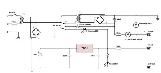
I came up with this circuit:
The Transformers will be(looking at the cheaper end parts, both will be around 7-10 VA):
- T1 : 230V -> 9V
- T2 : 230V -> 12V but in reverse.
The capacitors will be:
- C1 : 1mF 25V
- C2 : 47uF 450V
So will this circuit work and how should I improve it?
EDIT:
OK, here is an updated circuit taking into account all the replies.
I missed a lead on that regulator, also a resistor on the HV warning led, ignore, please
Some highlights of modifications:
- 7.5k Bleeder resistor, which should dissipate the power in a second or so after turning the HV off
- L7805 regulator for keeping the +5V clean
- HV on warning LED
- Fuses on all positive terminals
- It will be in either a plastic or wooden enclosure, to eliminate risk of touching anything inside
- All work on the circuit will be done after the HV is turned off, the warning LED unlit and voltmeter reads zero on panel
- T2 will be 18V
output terminals will be this kind or similiar:

all connections inside will be maniacally heat-shrink tube wrapped to counter any chance of a short
- will probably etch a PCB for that