3

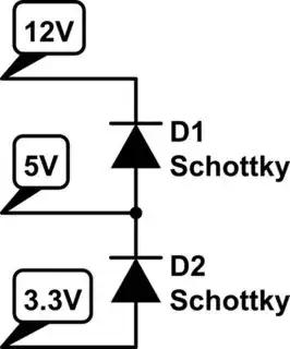
In my circuit, +12V would be supplied by an external power source. After two regulators, two more voltage sources (+5V and +3.3V) would be produced and supply power to the AD7682 ADC. Because of the maximum rating limit of ad7682, 3.3V needs to be down before 5V when I shut down the external power source +12V. Is there a good method to achieve this?

(I learned that some sequencer ICs can monitor the power sequence process. However, when I shut down the power source +12V, no power can be supplied to the sequencer ICs. So I think ICs are not suitable in my case.)

schematic

simulate this circuit – Schematic created using CircuitLab

Kevin Reid
  • 7,444
  • 1
  • 25
  • 44
billyzhao
  • 623
  • 6
  • 20

3 Answers3

2

Get 5 V and 3.3 V regulators that have enable, sometimes called shutdown, pins, then sequence them accordingly.

Properly sequencing the shutdown lines is not as trivial as it might appear at first glance. Probably the simplest way is to use a tiny microcontroller, like the PIC 10F200. This would have a single shutdown input, which then causes the individual shutdown signals to be driven accordingly in the right sequence with the right wait times between changes.

Olin Lathrop
  • 310,974
  • 36
  • 428
  • 915
  • Thank you for your answer. But one question: as I mentioned at the end of my question, +12V would be shut down first. And I only have three power sources. How can I use MCU to control it? Or maybe I can use 3.3V to supply power to MCU. But at that moment, 3.3V is also being shut down. Could MCU control its output pin so normally? – billyzhao Aug 30 '14 at 01:34
1

Depending on the current and and quantity of bypass capacitors, the secondary voltages can 'fall' at different paces. Sometimes, for sensitive components, Schottky diodes are placed between power supplies for avoiding inversions, which could occur in your example if the 5V crumbles faster than the 3.3V.

schematic

simulate this circuit – Schematic created using CircuitLab

TEMLIB
  • 3,347
  • 1
  • 14
  • 21
  • Thank you for your answer. This sounds good for my case.But does this method have any serious drawbacks? – billyzhao Aug 30 '14 at 01:35
  • I think this is a fairly classical method. This document from Texas Instruments may interest you : [link](http://www.ti.com/lit/ml/slup228/slup228.pdf) – TEMLIB Aug 30 '14 at 21:12
  • Yeah. It only list one drawback that if one source is forced to be 0 and another is forced to be high,then the diode would be destroyed. But I learned that the diode has parasitic capacitance, would this parasitic capacitance affect both voltage source? Do you know it? Thank you – billyzhao Aug 31 '14 at 04:06
  • Well, IIRC Schottky diodes have small parasitic capacitances. Besides, as power supplies are stuffed with decoupling capacitors... – TEMLIB Aug 31 '14 at 21:52
  • Besides, as you know, when 12V shut down, 5V outputs unknown value(maybe lower than 5V or maybe 0) when no diode there.And now, yes, a diode there. But would the output still be forced to 0V? – billyzhao Sep 01 '14 at 03:48
0

You can use a Programmable Power Supply Monitoring, Sequencing and Margining Controller as POWR1220. You can search for some device that supports 12V in your power supply or make a specific source from 12V to 5V to supply the POWR1220 and use it.