17

I am a student and my question is about finding the signal flow graph for a simple circuit.

enter image description here

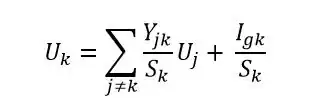
I found the above formula for a \$k\$ node having \$U_k\$ potential. In the book it is said that this is a base for building the signal flow graph using nodes potentials.

\$k\$ is the number of the node,

\$U_k\$ it’s potential,

\$S_k\$ the sum of the admittances from node \$k\$

\$Y_{jk}\$ is the admittance between \$j\$ node having \$U_j\$ potential and \$k\$ node

\$I_{gk}\$ is the algebraic sum of currents in the \$k\$ node (positive sign if he current enters in the node, negative sign if the current exits from the node)

Next , an example for this circuit for which we need to find the transfer function \$H(s)= \frac{U_2(s)}{E(s)}\$: passive RC circuit in double T connection

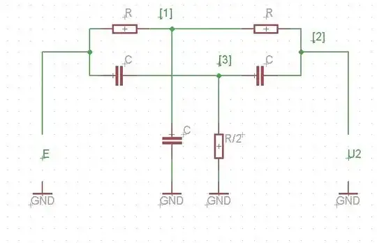
They write in the book the next linear system:

$$U_1S_1 = GE + GU_2$$

$$U_2S_2 = GU_1 + sCU_3$$

$$U_3S_3 = sCE + sCU_2$$

where:

$$\require {cancel} \cancel{S_1 = 2(sC + G)}$$

$$S_1 = 2G + sC$$

$$S_2 = sC + G$$

$$S_3 = 2(sC + G)$$

\$G\$ is the real part of the admittance \$Y_{jk}\$ or \$G = \frac {1}{R}\$.

From the above equations they find the equation of the potential in each node as:

$$U_1 = \frac{G}{S_1}E + \frac{G}{S_1}U_2$$

$$U_2 = \frac {G}{S_2}U_1 + \frac {sC}{S_2}U_3$$

$$U_3 = \frac{sC}{S_3}E + \frac{sC}{S_3}U_2$$

The resulting signal flow graph is:enter image description here

If the \$S_k\$ is the sum of the admittances from \$k\$ node, how they calculated \$ S_1 = 2(sC + G) \$

I understand for node 2: \$S_2 = sC + G \$ (because I have one resistor from node 1 to node 2 and one capacitor from node 3 to node 2).

Why for the node 1: \$S_1\$ expression is not \$S_1 = 2G + sC\$? It is wrong in the book?


Later edit: the correct expression for \$S_1\$ is indeed \$S_1 = 2G + sC\$.

Where are the currents from the first formula?


Later edit: that term is equal to zero.

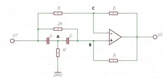
I need to understand because I have to find the signal flow graph for this circuit and based on the graph to find the transfer function using Mason rule: enter image description here

Hope someone can help me! Thanks in advance!

Best regards, Daniel

RinkyPinku
  • 536
  • 4
  • 16
NumLock
  • 169
  • 1
  • 10
  • As an aside, in North America we call this type of analysis as "Nodal Analysis". Hopefully you can find more homework tutorials under this name. We tend to use different variable letters. Instead of U for voltage we use V. ex. V1 is voltage at node 1. Personally I find it more convenient to keep resistances as resistances and not convert them to admittance. Could you please clarify what G is? I think you mean it is the current. – lm317 Aug 28 '14 at 05:08
  • 1
    \$G (Conductance)\$ is the real part of the admittance \$Y = G+jX\$ which is the inverse of impedance \$Z\$. The impedance of a resistor is \$Z=R\$, so \$Y=\frac {1}{R}\$ or \$G = \frac {1}{R}\$ (because \$\Im{Y} = 0\$) – NumLock Aug 29 '14 at 08:35
  • The question remains open. I want to find the transfer function \$H(s) = \frac {U_2(s)}{U_1(s)} \$ for the last circuit. – NumLock Aug 29 '14 at 08:45
  • Nicely formulated question. For the conductance, I would rather formulate it as \$Y=G-jB\$, and not use \$X\$ there. In this case \$B\$ is the susceptance, you can look it up on the internet. The minus sign is optional depending on your conventions. – WalyKu Nov 10 '14 at 13:22
  • u can get signal flow graph through the masons formula.. –  Dec 10 '14 at 17:33
  • This is a rant. I fully believe that **any** engineer author that wants to be called a professional in this day and age, absolutely needs to machine-generate the equations and drawings that make up any book that has equations, graphs, etc. This is especially true for books used for teaching. Maxima, Matlab or Maxima can be used to programmatically generate the circuit diagrams, equations, graphs, etc. so that there are no mistakes **by design**, not by chance. Typing stuff into Word and hoping that the editor or students catch the mistakes is just sloppy IMHO. – Kuba hasn't forgotten Monica Mar 09 '15 at 13:57

1 Answers1

3

Let me label the intermediate nodes in the circuit using the letters A, B and C as shown below.

enter image description here

The nodal equations at the nodes A,B and C can be re-arranged to get the three equations given below.

$$\begin{align}U_AS_A &= CsU_1 + CsU_B\tag1\\ U_BS_B &= \frac{G}{2}U_1 + GU_2+CsU_A\tag2\\ U_CS_C &= GU_1 + G'U_2\tag3\end{align}$$

Where, \$G=\frac{1}{R}\$, \$G'=\frac{1}{K}\$. \$U_A, U_B\$ and \$U_C\$ are the potential at the nodes A, B and C respectively. And \$S_A, S_B\$ and \$S_C\$ are defined as follows:

$$\begin{align}S_A &= G+2Cs\\ S_B &= \frac{3}{2}G + Cs\\ S_C &=G+G'\end{align}$$

Let the gain of the operational amplifier be \$A_{op}\$ and \$A_{op}\rightarrow \infty\$. Now the output voltage of op-amp can be written as:

$$U_2 = A_{op}(U_B-U_C)|_{A_{op}\rightarrow\infty}\tag4$$

From the equations (1) to (3) potential at nodes can be written as: $$\begin{align}U_A &= \frac{Cs}{S_A}U_1+\frac{Cs}{S_A}U_B\tag5\\ U_B &= \frac{G}{2S_B}U_1+\frac{G}{S_B}U_2+\frac{Cs}{S_B}U_A\tag6\\ U_C &= \frac{G}{S_C}U_1+\frac{G'}{S_C}U_2\tag7\end{align}$$

The signal flow graph can be drawn using the equations from (4) to (7) as given below:

enter image description here

You can apply the limit \$A_{op}\rightarrow \infty\$ while simplifying the calculations.

nidhin
  • 8,197
  • 3
  • 28
  • 46