2

as already questioned here, i am still working on peltier controllers. For that I am using a stepper motor driver (h-bridge) with a low-pass LC filter and the peltier element behind, as Olin Lathrop kindly explained. It works like a charm and is great for what it is designed for.

The schematic for that (I will add that to my older post as well): (made with circuitlab)

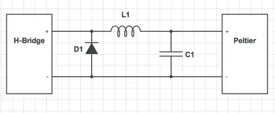
My problem is controlling temperatures close to the room temperature. By now, I have been using the h-bridge as a MOSFET only. That means I need to decide if the Peltier is going to cool my application, or heat it up. Since the h-bridge is capable of reversing the current I am trying to design a circuit that can go in both directions. The capacitor C1 is an electrolytic capacitor, so negative voltages would blow everything. I thought of using diodes somehow to detect current direction, but I am not really getting it. Can anyone help?

emma
  • 141
  • 2
  • 5
  • Peltiers are slow devices, why do you need D1/L1/C1 at all? You can simplify the circuit greatly by connecting the peltier directly to the H-bridge and using minimum periods measured in large fractions of a second. – Bryan Boettcher Aug 25 '14 at 16:54
  • 1
    A very good explanation for that was given by Olin Lathrop, see the link above. – emma Aug 25 '14 at 17:02

2 Answers2

3

I think you missed the point of the diode in Olin's original schematic. It was there to protect the bare MOSFET from the flyback effects of the inductor, and provide a path for the current to flow when the inductor is discharging its stored energy. To do that with an H bridge, you would connect diodes to the supply rails, but that is sometimes handled inside the bridge chip itself. Connecting a diode directly between the H bridge outputs is pointless — and potentially dangerous, as Andy pointed out.

schematic

simulate this circuit – Schematic created using CircuitLab

If you want to use large polarized capacitors in your filter, you just need to connect their negative terminals to ground. Each one will see only the correct polarity.

schematic

simulate this circuit

Dave Tweed
  • 168,369
  • 17
  • 228
  • 393
  • Will the body diodes in the MOSFETs in H bridge config do the same job? – Dirk Bruere Jun 01 '17 at 15:56
  • @DirkBruere: Yes, to some extent, although less efficiently. For large loads, external Schottky diodes are a good idea. – Dave Tweed Jun 01 '17 at 17:14
  • I am using IRF2903 MOSFETs. Their body diodes are rated 75A continuous and 1020A pulse – Dirk Bruere Jun 01 '17 at 18:06
  • @dirkbruere: At what Vf? The point is that any power dissipated in the body diode just adds to the total dissipation of the mosfet. An external Schottky dissipates less power (lower Vf) and moves that dissipation to a separate device, where it is more easily dealt with. – Dave Tweed Jun 02 '17 at 10:56
  • The device is rated for 70A and Vds=30, and I'm using it to provide a max of about 8A at 12V. It barely gets warm. Plus, the kickback from 33uH inductors running at 10kHz is not exactly large – Dirk Bruere Jun 02 '17 at 11:03
1

Firstly, what you have drawn does not constitute a H bridge - you have shown a ground connection on the "-" end of the peltier - this is a non-starter with H bridges. Neither will a H bridge driving a peltier need a diode (D1). In fact D1 will fry the millisecond the H bridge reverses.

So....

Use a standard H bridge that is driven from a high frequency PWM signal (not unheard of) and the smoothing components (L and C) need not be that big and the capacitor need not be a polarized type at all. Anything from 10 kHz upwards would probably do the job and many H bridge circuits work in excess of 100 kHz.

Here is a product that you can buy that might give you some ideas. It's called FTX300 and it's a H bridge that works with PWM and controls a peltier of up to 180 watts.

Here is also a Texas Instruments white paper that will help you design one too.

Andy aka
  • 434,556
  • 28
  • 351
  • 777
  • yea, the ground was a mistake. it is not actually in my circuit. for the diode (D1): until now i haven"t done any h-bridge reversing, so it didn't matter but at the same time didn't hurt to put one..but i get your point about the reversing.the thing with the high frequency PWM: right now the frequency is about 500Hz and it is getting quite warm already. i put a heatsink and a fan on top of the h-bridge ic, but i'm kind of afraid to move to anything in the kHz-range. instead, i moved down the cut-off frequency of the low-pass with a high valued C and L, so I'm at about 90Hz cut-off frequency. – emma Aug 26 '14 at 09:14
  • with my 500Hz PWM, it already gives me a small enough ripple. but again: i don't really see my big capacity being replaced by a non-polarized one. i'll see what i can get out of your links. – emma Aug 26 '14 at 09:23
  • If you have a H bridge and you are driving it then the diode is already busted because you cannot avoid reversing it when the H bridge switches - maybe you need to show what your full circuit is. – Andy aka Aug 26 '14 at 10:07
  • well, without reversing the current wants to continue to flow after it has been switched off, that is why i put the diode. it pretty much is my full circuit already.. – emma Aug 27 '14 at 11:35
  • The point you seem to be missing is that H bridges are not necessarily driven in both directions in some applications. The OP has chosen to drive his in one direction only, at least to start with. – Dave Tweed Sep 09 '16 at 23:09
  • 2
    @DaveTweed I answered this question when there was a ground connection shown on the peltier. If the OP has chosen to amend his diagram then that's his problem. If you want to downvote then please feel-free to go ahead and don't waste any more of my time with petty or esoteric comments. – Andy aka Sep 09 '16 at 23:33
  • This is a very old question. My comment was not necessarily for you, but for other users who might come across this question in the future and be confused by the fact that your comments are now obsolete. If you choose to waste time on it, that's on you. – Dave Tweed Sep 09 '16 at 23:37