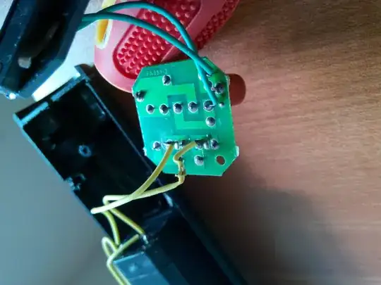
26

I disassembled a Chinese-made flashlight and found they use just capacitors to bring down the voltage instead of a transformer. They are using it to charge small lead-acid battery.

My question is how a capacitor alone can be used to bring 220 V down to 6 or 12 V?

Top-view

Bottom-view

Nick T
  • 12,360
  • 2
  • 44
  • 71
Ryu_hayabusa
  • 415
  • 2
  • 6
  • 10
  • 3
    Google this "Transformerless AC to DC power Supply" – Roh Aug 25 '14 at 11:25
  • 4
    See [Capacitive power supply](http://en.wikipedia.org/wiki/Capacitive_power_supply). – Rev Aug 25 '14 at 11:27
  • @Roh I searched everything else. – Ryu_hayabusa Aug 25 '14 at 11:47
  • 4
    Nasty design- I don't see any series resistor at all. At least they put a bleeder resistor (hidden behind the cap on the top photo) across the capacitor. – Spehro Pefhany Aug 25 '14 at 11:50
  • I just bought an RV and the manual says 6V of ripple is normal on the 12V battery charging circuit. Really cheap stuff, like this charger. – Bill Aug 26 '14 at 22:04
  • _"AC to DC without transformer?"_ - Note that AC to DC _always_ happens without a transformer. A transformer provides isolation and (usually) steps down the voltage, but it's AC in, AC out. AC to DC happens with a rectifier. In your case, the four black cylinders. – marcelm Mar 25 '17 at 17:31

3 Answers3

20

A capacitor is an impedance and at (say) 50 Hz, a 1 uF capacitor will have an impedance of 3183 ohms - if you put this capacitor directly across the AC (at 220 V), the current that would flow is about 70 mA.

OK, so it's not directly across the AC supply because it feeds a bridge rectifier and battery but it will provide a decent enough source of current to charge the battery. The voltage is limited by the battery itself.

Be aware that this type of circuit is not isolated from the incoming AC and stripping it down is OK providing you don't switch it on while still stripped down—the voltages are lethal.

Here's something like the circuit it uses:

enter image description here

Nick T
  • 12,360
  • 2
  • 44
  • 71
Andy aka
  • 434,556
  • 28
  • 351
  • 777
  • cap charges in half cycle so current may be ~~~ double what you calculate at 220 VAC. No? – Russell McMahon Aug 25 '14 at 12:51
  • @RussellMcMahon peak current could be about 1.5 x I guess but it's a crappy looking implementation without a real circuit so there's a lot of guesswork here. – Andy aka Aug 25 '14 at 13:10
  • In circuit you give as example, why do we need the `C1` capacitor (this is to have some impedance, so voltage lags current, but why?). Also : why do we need that Zener diode `D2` ? Isn't the bridge rectifier enough ? – tigrou Aug 25 '14 at 15:05
  • 1
    @tigrou the capacitor acts as a current limiter for the zener and the zener acts to limit the peak dc voltage - without the zener, the DC voltage would be peak AC voltage. – Andy aka Aug 25 '14 at 15:09
  • @tigrou In this scase there probably is no zener BUT the battery acts as a clamp making the supply a constant current source. – Russell McMahon Aug 26 '14 at 04:21
  • @andy - see comment above. – Russell McMahon Aug 26 '14 at 12:15
  • @RussellMcMahon I did say that the circuit I added was "something like" and I agree with the battery acting like a clamp as I also said "The voltage is limited by the battery itself". Pi*s poor design but what price on life LOL – Andy aka Aug 26 '14 at 14:43
  • @Andyaka How much will the capacitor dissipate? As much as a resistor of the 3183 ohms? – Guillermo Prandi Aug 28 '14 at 01:07
  • @GuillermoPrandi capacitors don't dissipate heat - they are reactive components - they just impede. – Andy aka Aug 28 '14 at 07:04
15

Suspect circuit:

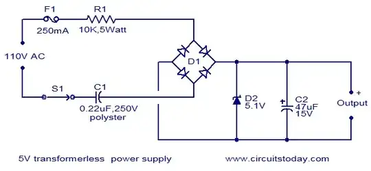
The circuit is probably as per Andy Aka but from the photo, it does not have the R1 high voltage series R, the zener, the fuse and possibly not the C2 output cap (which MAY be with the battery).

This is a "universal" light as the 400V rated cap may just about survive on 230 VAC, but the battery will be boiled twice as fast when using 230 VAC.

The missing R1 was intended to provide some voltage dropping but, more importantly, to provide some surge protection. If there are exposed power plug pins when mains is disconnected, touching them both will give you direct body access to the 20 mili-Joule which could be stored in the capacitor. Not enough to use as a defibrillator but certainly enough to ensure that you never voluntarily touch them ever again when charged [ask me how I know :-) ]. Unlikely to kill with single cap shock. Could. Muscle spasm or involuntary arm motion from shock may cause your arm to encounter nearby objects at speed and with force.

The diodes appear to be 1N4007, so they have done something right :-).

The missing fuse is meant to help in the event that the cap is not as AC mains rated as you'd hoped and fails short or some approximation thereof. The IN4007 diodes will probably make OKish standins.

The 330 Ohm resistor is probably used to power the power-on LED.

The battery is (apparently) used as the voltage clamp.
If it's a 6V battery then

$$I_{LED} \approx\approx = \frac{V_{bat}-V_{LED}}{R_{LED}} = \frac{6.5-2}{330} =\approx 14 mA$$

which is OK.

The capacitor is (labelled as being) 1.5 uF (155 = 15000000 = 1,500,000 NF)
This is "large".
Current from 110V mains is around 100 mA.

$$ I_{LED} \approx= \frac{110 \times 1.414}{2\pi \times 2fC} \approx= 100 mA \;\text{E&OE}$$

About double that at 230 VAC. 2f used as capacitor charges in half mains cycle and then flips back the other way on next half cycle.

Suspect battery charger:

Battery capacity unknown but from photo I'd doubt it was above about 500 mAh.
If battery is 500 mAh it will charge at around C/5 and if left charging overnight will be happily boiled well before morning UNLESS there is a regulator stage upper off.

If battery is 6V it is not unknown to connect strings of two white LEDs in series across the battery with no series resistors. This makes life exceeding exciting for the LEDs but works better than they have any right for it to.
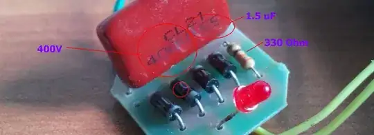
enter image description here

Suspect capacitor:

The capacitor is (labelled as being) 400V DC rated.
CL21 means metallised polyester.
It MAY be manufacturer rated as a Y2 or X1Y@ capacitor, which it should be in this application, but in fact its pot luck even if it does claim to be rated properly in this type of equipment. A look on "Alibaba" shows many visually similar caps (which must not be confused with "electrically similar" and SOME of these are claimed to be X1Y2 rated, but the majority are not. See a few references at end for interest.


Lessons:

Some interesting lessons can be learnt from such devices.
It lights the LEDs, charges the batteries and goes out the door at a good low price.
It will probably not kill anyone.
What's not to like?
:-(


Alibaba - MPE 1.5 uF, 400V or similar:

http://www.alibaba.com/product-detail/CBB-film-capacitor-1-5uF-400V_1344932478.html
No X rating or mention of AC
No X rating or mention of AC No X rating or mention of AC
No X rating or mention of AC - spec sheet.
No X rating - mentions AC without qualification in the fine print
A "real" example
And MANY more.

WARNING: ALL parts of this circuit and equipment powered by it should be considered to be at AC Mains potential at all times when connected to AC Mains. In this case the on/off switch and any metal parts are electrocution hazards.

Ricardo
  • 6,134
  • 19
  • 52
  • 85
Russell McMahon
  • 147,325
  • 18
  • 210
  • 386
  • Polyester film caps are typically "self healing" in the sense that if you *don't* limit the current they may blow the short away (at the cost of a small reduction in capacitance). Philips used to tout that 'feature'. – Spehro Pefhany Aug 25 '14 at 13:36
  • 2
    @SpehroPefhany Yes. If you bought them from a known reputable manufacturer via a traceable supply chain then they may be what you thought you bought, may have ratings you expected and on the other side from in the photo may have certifications and comments about AC ratings and X1Y2 etc. | Whereas if you got them inside a device that takes the shortcuts this one does one may not be 'quite so sure' [tm]. | But, I know you know that :-). – Russell McMahon Aug 25 '14 at 15:04
0

Polyester Film Capacitors are NOT DC capacitors, they are AC caps and can be used feeding either lead to a hot leg. They are used for many things, including cheap step down circuits, smoothing circuits, as motor run capacitors, and motor run caps use alone means they are AC capacitors. Just because something is rated at WVDC does not mean the caps are not capable of ac use, this only gives us the "working voltage using DC power". The reason these caps are rated with DC is because they can be used in high frequency circuits, but calculations must be used to determine the voltage at the AC frequency thrt will be used before assigning any cap that AC rating. If the cp is designed for high frequency use, you will NOT see the ac ratings, only WVDC and this doesn't mean it is only for dc use. Any bipolar self healing capacitor or a poly film capacitor, mica, or metallized caps are all rated in DC working voltages because other variables are needed to rate these with AC voltages. Here are the correct formulas to figure out what they could handle in ac real world environments, and the reasons why this is the case.

For a given application, the power dissipated in a capacitor can be calculated from the formula P=i² R, where P = the power in watts, i = the rms current through the capacitor and R = the Equivalent Series Resistance (ESR) of the capacitor. Then i= 2 pie fCE, where f = the frequency in Hertz, C= the capacitance in Farads and E = the rms voltage applied. Finally R= d/(2 pie fC), where d = the dissi-pation factor. Combining these three equations, the final power formula derived is P=2 pie fCE²d.

It is necessary to determine the values of capacitance and the dissipation factor, assuming that we know the applied voltage and frequency. Note these values are typical and will vary from one manufacturer to another. The cap changes due to voltage can also be modified by the manufacturer to meet a given application requirement.

After the above corrections to capacitance and dissipation factor are made based upon the circuit voltage and frequency, the actual power consumption in the capacitor can be calculated from the formula P=2 pie fCE²d. Note that both the capacitance value and the frequency directly affect the power for a given voltage. This is why it is not possible to assign a generic AC rating (or a factor to apply to the DC rating) for capacitors. Only when these values are known (as in fixed value 60Hz power applications) can this be done.

An AC capacitor could be used for current limiting means in series, and if you used a 100 uF 350vac capacitor through an AC hot line at it's rated frequency, this would result in only 4 or 4.5 amps output because the cap could only allow this energy through as it functions in a very specific way in series. If ac ws connected through an electrolytic "dc" cap that is polarized, the cap would either explode when the waveform oscillates or it would do nothing and not allow energy to pass while the ac cap does.

Placing the cap in parallel with motor leads literally recovers the reactive power or the back emf built by the motor during the open coil position it hits within it's rotation and when it does this, the magnetic field passing the coil generates electricity in a much higher voltage range that is part of 2 things. The motor will generate power for this small period of time while the cap immediately collects it and dumps it into the next coil the commutator connects to, dumping it's conventional pulse at a very high amperage, causing a reduction in amps used, also, the result will spin the motor a bit faster. DC capacitors , or electrolytic polarized caps can't be used in these scenarios, they will cause explosions or fires.. stay away from them, they are built too cheaply with thin paper, aluminum foil and silicone oil or standard organic oils.