This looks like a type of switching regulator that has a constant "on" period and variable "off" period. Once the regulator has measured the output voltage to be correct (at its upper limit), and, in the absence of significant loading effects on the output, the switcher switches off and the output voltage decays until the lower threshold of operation is reached whereupon it repeats the cycle. Sometimes one "on" period isn't enough to restore the voltage to the correct top limit and you'll see several pulses all close to each other.
If you need a better waveform there are better switching topologies but, you are unlikely to be able to determine that from an amazon web-page.
If you load the output with more capacitance, the spikes will appear less frequent but there may be more "on" periods closely grouped in order to restore the voltage to the upper limit. It's called a bang-bang type regulator and relies on the output waveform ramping up and down a little bit. The spike is usually related to resonance of the switching inductor but can be due to bad PCB layout, poor choice of capacitor in the output stage or your o-scope telling you something that isn't actually there (magnetic induction).
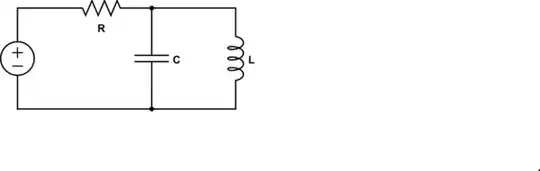
A way around this might be to use an output resistor of a few ohms and another capacitor but obviously the "few ohms" are going to lose some voltage when a real load current is taken. An inductor might help but without knowing the timebase of the picture it's difficult to guess at what value.