I am trying to make a line follower robot using LM324 as comparator, but I cannot understand the theory or the explanation of this circuit. I also don't know how to calibrate it with the IRs.
I am trying to make a line follower robot using LM324 as comparator, but I cannot understand the theory or the explanation of this circuit. I also don't know how to calibrate it with the IRs.
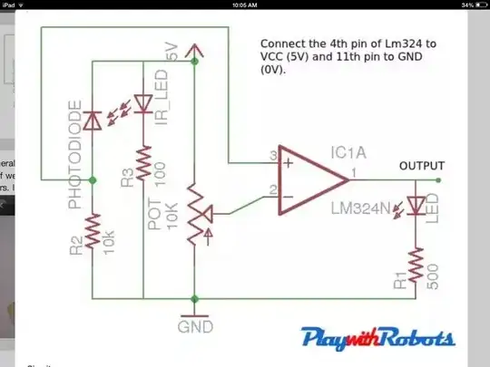
That drawing isn't very well laid out - the LED should have been drawn to the LEFT of the photodiode to make it a little more clear.
The LED generates light full-time. The photodiode may or may not pass current, depending upon whether it can "see" the LED, so the voltage available between the photodiode and its resistor will rise and fall as the photodiode "sees" and "loses sight of" the LED.
The LM324 is used as a comparator; when more voltage is present on Pin 3 than the voltage on Pin 2, it turns on, and Pin 1s voltage rises to VCC.
When the photodiode turns on, it'll pull the voltage at Pin 3 high. When it turns off, R2 will pull that voltage low.
The potentiometer is used to adjust the point at which the 324 turns on & off reliably, as a reference voltage. It should be adjusted such that the voltage at Pin 2 is higher than Pin 3 when the photodiode is turned off, but lower than Pin 3 when the photodiode is turned on.