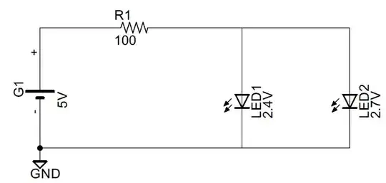
If two LEDs with different forward voltages are connected as shown, then for idealized electronic parts, the LED with the higher Vf will allow no current through it, and will not light up at all. The LED with the lower Vf will be the only one lit up.
simulate this circuit – Schematic created using CircuitLab
To understand this better, note that the voltmeter as shown above will read 2.4 Volts, the forward voltage of LED1, and that is insufficient to light up LED2.
To calculate current drawn from the battery (first diagram in the question), the voltage drop across the 100 Ohm resistor passing said current, must equal the difference between supply (5 Volts) and Vf (2.4 Volts):
$$I = \frac{V}{R} = \frac{5.0 - 2.4}{100} = 0.026 A = 26 mA$$
LED1 will also thus have 26 mA flowing through it, and LED2 will have 0 mA.
When using real world components, the behavior is marginally different. Note the V-I graph for this 2.7 Volt blue LED:
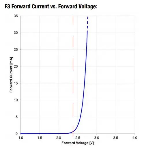
Even though the datasheet indicates a forward voltage of 2.7 (typical) to 3.6 Volts, the actual current it will allow at 2.4 Volts, shown by the red line, is just under 1 mA going by the graph. Of course, the graph is an approximation. Even two LEDs from the same production batch will have slightly different actual V-I curves, with temperature variation adding yet another set of variables.
Be that as it may, this ~ 1 mA current through LED2 will reduce the current drawn by LED1 by approximately the same amount, if one were to simplify things somewhat. The exact currents through the two LEDs can only be determined experimentally, due to the environmental and manufacturing variables affecting the various parts.