4

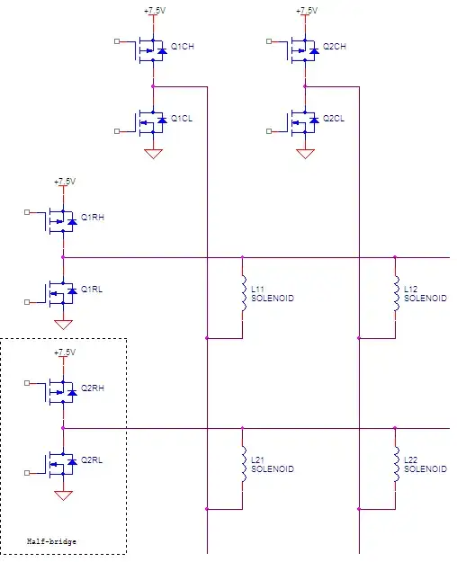
I'm building a circuit to control a flip dot display, which is basically a matrix of solenoids which you control with bidirectional current across the 25 columns and 7 rows of the board.

The attached schematic shows the circuit so far - I'm using a bank of H-Bridges to control the columns, and they switch polarity depending whether I want to flip a particular dot one way or the other.

The challenge comes with controlling the rows, at the bottom of the image. If I'm targeting a particular row, the positive voltage has to go down one path, and the negative down another. So I imagine I'm looking for a bidirectional DC solid state switch that can handle a peak of about .5A.

Any suggestions on how I should implement that part of the circuit? Electromechanical relays are not good because these switches will be used thousands of times a day (in a clock). I also need to be able to handle up to 0.5A.

bidirectional circuit

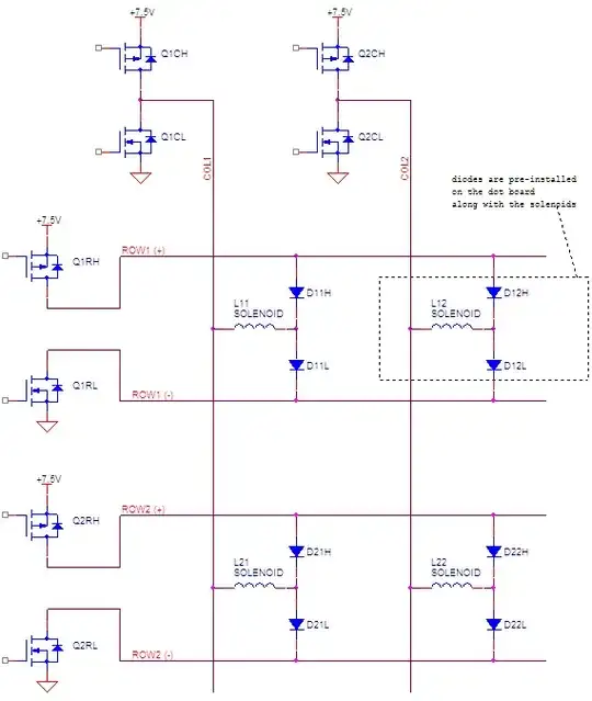
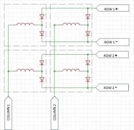
Edit: I've added a more accurate schematic for the flip dot board (25 columns, 7 rows)

enter image description here

update:

Thanks to all the ideas folks contributed to help me solve the problem. I finally finished the flip-dot clock project - you can check it out at http://www.dhenshaw.com/dottie

If there's interest I'll post a schematic of what I built (I'd also have to draw it first!)

Nick Alexeev
  • 37,739
  • 17
  • 97
  • 230
David
  • 43
  • 5
  • Both sides of the solenoids are H-Bridges. You already have the technology you need. – gbulmer Aug 18 '14 at 13:55
  • So when all power is off, the flipped dots hold their positions whether "on" or "off"? And by extension, that means that only a pulse is needed to change the orientation of any one dot, with no requirement for sustained power to the solenoid? EDIT: will these solenoids even **tolerate** being energized full-time? – TDHofstetter Aug 26 '14 at 04:40
  • Correct - a 100ms pulse flips a dot and it then stays in place. You could keep them energized all the time, but that would be a waste of electricity (9v @ 350mA) – David Aug 26 '14 at 18:12
  • I'd be interested in your final schematic whenever you have a chance to draw it up! – cristoper Oct 25 '14 at 16:04
  • ...did you manage the final schematics for Dottie? Would be very interesting for me, because I just got some 5x7 flip dot units. Cheers Udo Seligmann / Wuppertal, Germany p.s. is Dottie still running ok? – Udo Seligmann Jan 18 '17 at 16:52
  • Unfortunately the link to dottie is not working anymore :( – needfulthing Jun 17 '19 at 16:21
  • Sorry @needfulthing, the new web server is case sensitive so some old URLs don't work. Here's another link to get you to Dottie - who still works perfectly - http://dhenshaw.net/art/Dottie/start.html – David Jun 19 '19 at 02:51
  • Respect, this is about the biggest breadboard project I have ever seen. I wouldn't dare to use them this way because of the wobbly connections they provide, but cool anyway :) I really would love to do something with a flip dot display but the prices for them are quite high, at least on the pages I found. – needfulthing Jun 19 '19 at 16:06
  • @David: very cool project. I appreciate the time and effort you put into this. :) – PStechPaul Oct 14 '22 at 23:36

2 Answers2

6

David, while you may be able to find the appropriate switches and make your current approach work, I think there is a neater solution to your problem.

enter image description here

Each row and column in the matrix can be high, or low, or floating. This gives you random access to each solenoid, so you can run current through one solenoid in either direction, while no current is running through other solenoids.

I drew the half-bridges with MOSFETs, but they can be implemented in other ways too.

update:

enter image description here

The circuit in the dot board with the diodes seems a bit odd to me. It would still require nTransistors = 2*nRows + 2*nCols, but now the dot board has 2x connections per row instead of 1. I wonder what the rationale of the dot board designers was. I also wonder if I’m missing something.

Then again, we’re situated roughly in the same neck of the woods. Perhaps, I can physically look at your dot board.

Nick Alexeev
  • 37,739
  • 17
  • 97
  • 230
  • Thanks for your suggestion - it makes sense, except that the solenoids (which are on a complicated PCB with built-in diodes) aren't wired as simple as this... each solenoid has one line to control column, but two lines to control the row, which are dependent on voltage polarity - like my diagram above. I did try to wire it per your suggestion, but it didn't work (nothing flipped either way). I've manually wired up some pushbuttons & got the dots to flip either way, so I'm pretty sure my schematic depiction is accurate (but obviously not my electronics implementation!) – David Aug 19 '14 at 03:29
  • @David It sounds like each one of your dots has 3 connections and 2 separate solenoids. But in that case, it seems odd to me that it has 2 solenoids per dot *and* you need to reverse polarity. Do you have a datasheet for your flip dots? – Nick Alexeev Aug 19 '14 at 03:40
  • Sorry for the delay... so to be more specific, I uploaded a schematic that shows how there's one "column selector" line but two row selector lines. The PCB includes the diodes. – David Aug 26 '14 at 03:05
  • @David I have updated my answer. Have a look. – Nick Alexeev Aug 31 '14 at 04:43
  • In the first schematic in this answer, you'll find that when you try to activate L11, a parasitic current will also flow through the other three. The parasitic path has 3x resistance of L11, so you'll get 1/3 the current, but that still may be enough to flip a solenoid. I actually just built an array like this of 5x8 only to find that I was unintentionally actuating solenoids that share a row and column. It looks like the diodes in the second schematic save you from this issue – miles60 Mar 21 '19 at 22:07
  • see: https://electronics.stackexchange.com/questions/265399/what-is-the-purpose-of-diodes-in-flip-dot-displays?noredirect=1&lq=1 – miles60 Mar 25 '19 at 21:05
1

This one fell right off the bottom of the page & got forgotten.

David, if you already have your enableable H-bridge, then all you need to add to your original drawing is one pair of diodes per cell to ensure that negative voltage drives the cell to one state and positive voltage drives the cell to the other state.

The key will be "enableable". When you're not actually driving any cells to any new state, the whole H-bridge will need to drop power.

TDHofstetter
  • 1,292
  • 6
  • 12