-3

So, from I can tell from the answers I received to my previous questions, if I want to lower the output current from a battery, I could put a resistor in series with my circuit.

But wouldn't that only lower the current by some amount? If the battery output was lower than expected, it would be reduced farther by the resistor. And a greater than expected output would still be higher than the target current?

Another possibility is that I am hopelessly confused by all this, and should go find a nice book on EE.

edit:
I should have said that the circuit I am trying to make, requires a fairly steady current flow, with a maximum current and a minimum current. (The minimum current is not super important, but it can't exceed the maximum current.)

edit: I should probably give a few more details. My coil/s should have 0.97232Ω of resistance, should use about 7.263 meters of wire.

edit:
Could I use a current mirror?

enter image description here

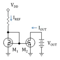
With the reference current set to what I need my battery output to be?

CoilKid
  • 261
  • 1
  • 4
  • 18
  • Look for constant current circuits. There are fairly simple ones, if you don't require it to be very stiff. But first things first - [get a book](http://electronics.stackexchange.com/questions/616/basic-electronics-book). – Nick Alexeev Aug 16 '14 at 22:40
  • I have a book, but I didn't see anything on keeping a current supply constant. Perhaps I was looking in the wrong place though. – CoilKid Aug 16 '14 at 22:43
  • @CoilKid - read my answer to your previous question. IMHO this question is not relevant until you have solved your initial problem. You are asking for answers to problems you do not have. I think you are confused about the fundamental concepts of voltage, current and resistance. I don't think you need an electronics book. I think a good place to start is a high-school Physics or Science book. AFAICT, most of the links on this [Basic Electronics boks](http://electronics.stackexchange.com/questions/616/basic-electronics-book) page are too advanced to help you resolve your fundamental confusion. – gbulmer Aug 16 '14 at 23:02
  • @CoilKid Here's a benign question for you. Do you understand how [these circuits](http://en.wikipedia.org/wiki/Current_limiting#Single_power-supply_circuits) work? – Nick Alexeev Aug 16 '14 at 23:09
  • Admittedly, not entirely. If you're trying to figure out if helping me is a wast of time, then fine. I appreciated the help I have received. ;) – CoilKid Aug 16 '14 at 23:14
  • @CoilKid - It is helpful provide a link to your previous question in your new question. Further to avoid any ambiguity or misunderstanding: there is no indication in the information you provided in your previous question that you need to lower the current from the battery in any other way than increasing the resistance of the solenoid coil. I suggest you sort that out first. Then once the answer to that is clear you will have some concrete facts to ask further questions. – gbulmer Aug 16 '14 at 23:29
  • @CoilKid This was a formative question (as opposed to a summative assessment). I was only trying to help you assess your understanding of things, and (possibly) provide you with a motivating example, which might help you while you are reading your book. – Nick Alexeev Aug 16 '14 at 23:37
  • Okay, I shall keep that in mind, in the future. Thanks. I suppose what I need would be some sort of "Active" current regulation. – CoilKid Aug 16 '14 at 23:38
  • @CoilKid have you read the answer to http://electronics.stackexchange.com/questions/125316/batteries-output-current-limiting? So far, you have not given us enough information to deduce anything. Find the answer to your first question first. – gbulmer Aug 16 '14 at 23:42
  • @gbulmer So... What do you need then? I thought I gave input voltage, current, resistance of circuit, and required current. :/ – CoilKid Aug 16 '14 at 23:50
  • @CoilKid - "I thought I gave input voltage, current, resistance of circuit, and required current." No you have not. You have only given the battery voltage, and the current. I have explained how to calculate the resistance. I have given you the resistance which achieves the current for that voltage. You haven't made the coil. You have not explained why that coil resistance doesn't give the required force. I have explained how to adjust the coil force if it generates too much force, without changing the resistance. So you need to explain why the answers given do not answer the question. – gbulmer Aug 17 '14 at 00:40
  • If this is still for the solenoid... and you plan to wind the solenoid yourself... then the simple thing to do here is calculate how much wire of what gauge it will take to draw X amount of current from the available voltage, and wind your solenoid with that length of that gauge wire. Then the solenoid's current draw will be known and self-limited, and the solenoid will get maximum benefit of the power available to it. – TDHofstetter Aug 17 '14 at 00:41
  • @gbulmer One of us does not understand. Given that you know more about electronics, its probably me. I know the resistance of my coil I can't really change the coil much. What I need is an active current regulator on the battery. The force from the coil depends on the current going through it, and the number of turns. I cannot change the number of turns, so I must limit the current. Also, I think part of the problem is I have not put the numbers in this question. Therefore: 0.97232Ω(circuit), #26AWG(Coil gauge),9.6V(battery),1000mAh(battery), 1.0A required(steady)current. – CoilKid Aug 17 '14 at 00:57
  • @CoilKid - If you have all of that information, then put it into the text of your [*first* question](http://electronics.stackexchange.com/questions/125316/batteries-output-current-limiting); it is not there yet. Include the force calculation too, because that constrains those values. Also, include any other constraints, for example explain what causes the wire diameter to be fixed at 26AWG. Then I think people have a 'fighting chance' of answering your first question. Then, hopefully, you will have the *facts* for this question, if it is needed. – gbulmer Aug 17 '14 at 01:11
  • @gbulmer You want the force calculation? The only relevant variables here would be the number of turns and the current through it. Well, as to the constrained to #26AWG is mostly the price of copper. Also, its the volume of the coil. I have a few size requirements. I think I could go another gauge or two larger, but the smallest I can would be best. – CoilKid Aug 17 '14 at 01:27
  • @CoilKid Dude, how can you seem to accomplish so little and write so much in the process? Make some damned experiments already. Get your hands dirty. – Nick Alexeev Aug 17 '14 at 02:00
  • @NickAlexeev I don't have the materials right now. I'm designing this stuff right now. Anyway, thanks for the help. – CoilKid Aug 17 '14 at 02:19
  • WOULD the current mirroring work? If it would it would help quite a bit. Could someone please tell me? It seems like it should work, but I'm not sure. If it doesn't I should probably keep researching... – CoilKid Aug 17 '14 at 02:41
  • "Pluralitas non est ponenda sine necessitate ("plurality should not be posited without necessity"). Refine your 1st question and do not start over. | Any sensible solutiuon with the coil resistance that you propose (which does not seem to be a good one) MUST use a switching regulator. 1 amp in about 1 Ohm drops 1 volt. The other 8 volts from a 9V battery would be wasted as heat with a linear regulator. So Psolenoid = 1 x 1 = 1 Watt. P wasted = 1A x 8V = 8 Watts. The 2 transistor relay driver circuit I suggested does EXACTLY what you want and is cheap and simple enough. You could use a .... – Russell McMahon Aug 17 '14 at 14:05
  • .... SR (switching regulator) IC or buy a working device from ebay for about $5 or less. – Russell McMahon Aug 17 '14 at 14:05

1 Answers1

0

In your other question you say that you are powering a solenoid wound with 26 AWG wire, and you want it to draw 0.7~1.0 Amps. The only thing we don't know is how much resistance that coil has, which is determined by the length of wire required to get the force you want.

Once you have determined the resistance of the coil, you can then work out how much resistance is required to limit the current. For example, if your battery puts out 9.6V then you need a total of 9.6V / 1A = 9.6 Ohms to limit the current to 1A. If the solenoid coil measures 2 Ohms then you need an extra 7.6 Ohms in series with it. If the battery voltage then drops to 8V the current will be 8V / 9.6 Ohms = 0.83 Amps.

A typical 1000mAh 9.6V HiMH battery has a voltage range of about 10.8V (fully charged) to 8V (flat) at 1A, so if you choose the resistance required to give 1A at 10.8V then the current will drop to 0.74A at the end, well within your requirements. Thus a simple resistor is all you require to limit the current. Now go and measure the resistance of that coil!

Bruce Abbott
  • 55,540
  • 1
  • 47
  • 89
  • 0.97232Ω for the coils. (I calculated out to 7 decimals :/) – CoilKid Aug 17 '14 at 01:00
  • I appreciate the help. I can't use a resistor to limit the current though. I need something that is more of an "Active" current regulator. I was thinking of a current mirror? – CoilKid Aug 17 '14 at 04:17