0

I am making a simple motorised blind controller, which I want to have a "safety cut out" when it gets to its fully closed/fully open state. (So the user doesn't strain the motor keeping their finger on the button when it is open/closed.)

I'm a bit of a noob, but it seemed fairly straightforward in terms of logic.

Basically there will be a reflective IR sensor at the top, and at the bottom (level with the fully closed position of the blind). The logic is that when the user presses the up button, if the top sensor is high (i.e. the blind is in front of it) the motor will run until either they let go of the button or the sensor goes low (because the blind has passed it).

Similarly, if they press the down button, the motor will run in the opposite direction (controlled by an L293D chip) if the bottom sensor is low (i.e. not covered by the blind). Again this continues until the sensor goes low (blind has reached the bottom) or they let go of the button.

I've drawn up a schematic, and I think the logic is right, but I wanted to check if I need to protect the chips with resistors. I'll power it with a 5V 700mA mobile phone charger for the 5V supply, and I'll also need a separate 12V supply for the motor. (Will join the grounds from both).

Is there anything else I am missing, or any noob gotchas I need to be aware of?enter image description here

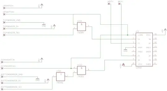
Also - if I have made any howlers on the schematic layout / broken any major conventions, please feel free to put me straight! (Can't figure out how to attach a clearer version as it looks like it has been scaled down to fit.)

Ben
  • 299
  • 5
  • 11
  • Please tell us what reflective sensors you intend to use. As it stands, that circuit has a lot of issues to be resolved if those sensors are the 'standard' analogue type. – gbulmer Aug 14 '14 at 13:06
  • These are called **limit** switches or sensors. – Passerby Aug 14 '14 at 23:13

1 Answers1

1

Are the reflective sensors the only components missing from this schematic?

What are the reflective sensors? Do they provide a digital output, or are they ordinary analogue parts? If they are analogue, and there are no other parts, then there are some issues.

I assume this is for window blinds, in which case, it needs to deal with the possibility of the sensors being blinded or confused by sun-light.

I'd expect to see something controlling the emitter current, to modulate the reflective sensors light source to avoid 'sun' problems. Some sensors might do that internally, but it would help us t see the part number for that sensor.

How is the reflective sensor signal derived? For an analogue sensor, I'd expect to see a resistor, or something so that the sensor can provide a voltage dependent on the intensity of light.

I'd concerned about switching logic gates with an analogue signal. I'd have expected Schmitt triggers to convert the analogue voltage to a logic level.

Edit: I would expect to see pull-up or pull-down resistors connected to the switches.

When switches are open-circuit, they have no defined voltage on one of the pins. That voltage could be set by static, or radio reception. The inputs for many modern CMOS chips requires a very, very small current. So they could be switched by that 'stray' current.

Normally, the connection to the switch which is going to change (when the switch is pressed) has a pull-up resistor connecting it to V+, or pull-down resistor connecting it to ground. That resistor pulls the state of that connection to a known 'default' value, and hence prevents 'stray' electricity accidentally triggering the circuit. When the switch is pressed, the short circuit 'beats' the resistor and defines the voltage on that connection.

Edit: This issue is not about debouncing. The circuit might work okay even if the switches did 'bounce'. The issue is having connections from open switches with no defined voltage value. Every single throw switch must have a pull-up or pull-down resistor, to reliably define the voltage on the open-circuit wire. I might debounce the switch too.

I'd expect to see some decoupling capacitors across all of the ICs. When an IC switches, it will require a 'pulse' of current. That pulse could cause a glitch in other chips using the same power supply. To ensure stability across the whole circuit, that pulse is supplied by a small capacitor connected very close to each chip.

Edit: What is a decoupling capacitor and how do I know if I need one? looks like it covers all the bases.

I'd like to see some capacitance across the power supply input.

I'd be tempted to use one power source (e.g. 12V) for the entire circuit, and use a voltage regulator to step down to 5V. The chips only under a few 10's of mA on the logic 5V supply, so using an appropriate linear regulator should be okay.

gbulmer
  • 10,040
  • 20
  • 29
  • Thanks - really useful feedback! The IR sensors are these: http://ebay.eu/VmMwjs so it's a digital signal. – Ben Aug 14 '14 at 14:20
  • Sunlight should be OK as the blind is for a basement window, with no direct sunlight coming in. – Ben Aug 14 '14 at 14:21
  • The pull-up / pull down resistor across the switch makes sense. Will look into this! – Ben Aug 14 '14 at 14:24
  • Voltage regulator also makes sense here. Will add that... – Ben Aug 14 '14 at 14:26
  • The only thing I'm not sure on is the capacitance. Can you point me in the right direction for more info / best practice on this? Do I just need a capacitor on the 5V pin on each chip, or is it more complex than that? Similarly for the input power supply? – Ben Aug 14 '14 at 14:28
  • How do I work out the right capacitor values? – Ben Aug 14 '14 at 14:29
  • Finally, just wanted to say thanks for taking the time to reply - really appreciate the feedback! – Ben Aug 14 '14 at 14:29
  • @Ben - their doesn't need to be *direct* sunlight. Our eyes are amazing, so it is very easy to forget that indirect sunlight (daylight) is so bright that we can easily read, forget to switch off a light because it is drowned out by daylight or fail to see an indicator light. What would happen if both sensors saw enough light to trigger 'on'? Further because it is a basement, when the light is switched on might that confuse the sensors? If you really want to do this without modulation, then do some experiments in the specific location; I wouldn't but it is true that YMMV. – gbulmer Aug 14 '14 at 14:31
  • @Ben - Yes, you put a decoupling capacitor across the voltage and ground pin on each chip. the general recommendation for local decoupling capacitors is 100nF ceramic with a voltage rating at least 2x the voltage rail. They typically cost a few cents/pence. There should be a good answer on this site. – gbulmer Aug 14 '14 at 14:32
  • Great stuff - thanks again. This helped me with your suggestions on debouncing, too: https://www.youtube.com/watch?v=tmjuLtiAsc0 – Ben Aug 14 '14 at 14:44
  • @Ben - debouncing the buttons would be nice, but your circuit would work without it, just not as cleanly. The real issue is the connections between the switches and the logic gate have *undefined* voltages when the switches are open, and could be random. The circuit might randomly open or close the blinds. It'd be 'spooky' :-) – gbulmer Aug 14 '14 at 14:52
  • Ha! Might scare the kids. The debouncing example in the you-tube clip has a pull-up resistor on, so I guess this would "cure" the spookiness? – Ben Aug 14 '14 at 14:56