I'm currently trying to build a DC voltage source from an AC source to a school project. The circuit worked fine when it had no voltage regulator, as it was just a transformer + full-wave rectifier + capacitor filter; the output was a DC voltage varying from 23V to 21V.
The desired output is 15V. So, the goal is to use a regulator (which is actually a 10V-Zener in this case) and a controller built using a comparator amplifier to keep the output voltage as closest to 15V as possible; there's also a NPN BJT in amplifier's output that's there to supply the needed current to the load - it's written 'Carga' on the load, which means Load in portuguese.
So, the final circuit is the following:
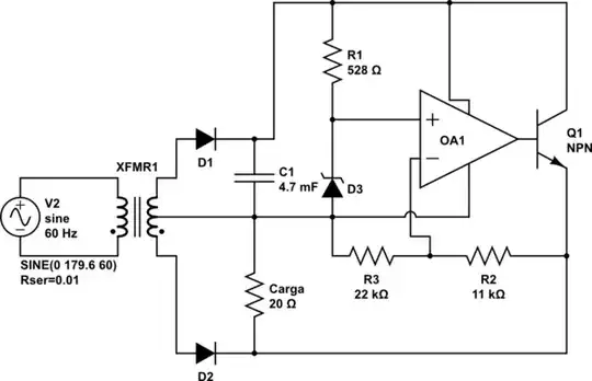
simulate this circuit – Schematic created using CircuitLab
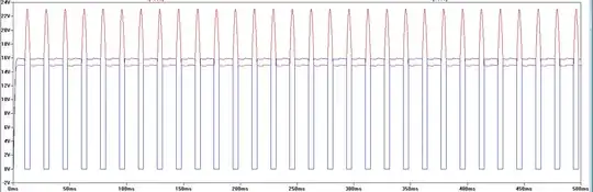
The problem is that when I run the simulation and check the load's voltage, it's 15V for an interval of time and then it suddenly goes to 23V, which is the not-regulated-circuit output voltage; then it goes back and do it all over again. I guess the transistor is actually going into the saturation region of operation, and I really don't know why. The result of the simulation is in the image below; the red lines are the output voltage and the blue lines are the amplifier output voltage.
If anyone needs I can upload the .asc file (LTSpice schematic), but I guess it's just a stupid mistake I'm doing.. anyone got any idea?
I really appreciate any help. Thank You.
edit: for anyone who needs a better schema of the regulator, which is my problem: https://i.stack.imgur.com/iDpwf.png. sorry for the bad drawing.