37

The new USB Type C connector doesn't have a physical reverse polarity protection any more. You can plug it in any way you want on both ends, there is also no A and B end any more, it's all the same.

So how does this new USB type handle that the polarity doesn't end up being reversed or signals being routed to the wrong point?

Is there some sort of routing going on in the connector and the devices don't have to handle anything and can be sure the polarity is always correct?

This is assuming that not half the signals in the cable are redundant.

Type C connector and receptor

timonsku
  • 1,368
  • 3
  • 14
  • 30

3 Answers3

40

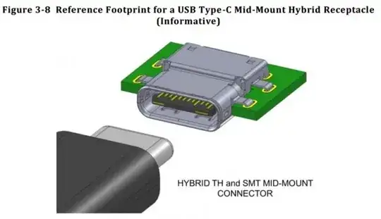
Below is the pinout for the receptacle:

GND  TX1+ TX1- Vbus CC1   D+   D-  SBU1 Vbus RX2- RX2+ GND
 |    |    |    |    |    |    |    |    |    |    |    |
=+====+====+====+====+====+====+====+====+====+====+====+=
 |    |    |    |    |    |    |    |    |    |    |    |
GND  RX1+ RX1- Vbus SBU2  D-   D+  CC2  Vbus TX2- TX2+ GND

You will note that all the pins are rotationally symmetric, so if you flip the connector, TX1+ connects to TX2+, TX1- connects to TX2-, etc. and most importantly, Vbus and GND always match up.

The trick lies in the controller and cable -- the CC pins are used to detect orientation, at which point the controller routes appropriately:

2.3.2 Plug Orientation/Cable Twist Detection

The USB Type-C plug can be inserted into a receptacle in either one of two orientations, therefore the CC pins enable a method for detecting plug orientation in order to determine which SuperSpeed USB data signal pairs are functionally connected through the cable. This allows for signal routing, if needed, within a DFP or UFP to be established for a successful connection.

Source: blogspot link Source: blogspot link

As you might imagine, the cables are going to be a fair bit heftier due to the extra wires.

  • A minimum of 15 wires plus braid required for full-featured Type-C (i.e. USB 3.1 -- recommended 4-6mm outer diameter)
  • 10 wires plus braid for legacy Type-C USB 3.0/3.1 cables (intended to connect to Type-A or Type-B on the other end -- recommended 3-5mm outer diameter)
  • For USB 2.0 or earlier, whether connecting to Type-C or a legacy type on the other end, the usual four wire configuration is permitted (recommended 2-4mm outer diameter)

Source: USB 3.1 Specification @ usb.org -- specifically, the Universal Serial Bus Revision 3.1 Specification PDF available for download at the top of the page)

Also a great blog post explaining all the details about the Configuration Channel pin:

http://kevinzhengwork.blogspot.de/2014/09/usb-type-c-configuration-channel-cc-pin.html

Archive.org (in case it goes offline)

timonsku
  • 1,368
  • 3
  • 14
  • 30
Doktor J
  • 1,063
  • 8
  • 15
  • 4
    Why not have it exactly rotationally symmetric and not have to worry about orientation whatsoever and cut down on pin count?? – ACD Aug 13 '14 at 18:25
  • 4
    @ACD to do that, you'd have to add four more wires after removing the two CC wires, which is two more than the wiring that detects orientation. – Funkyguy Aug 13 '14 at 18:36
  • 3
    @Funky I meant why care about orientation at all. If you made the connector like this instead: http://imgur.com/VKqyvJg it's the same number of pins and no need to have a controller change routing if it's plugged in one way or the other. – ACD Aug 13 '14 at 18:57
  • 3
    @ACD In the image you linked, half of the superspeed signals are omitted. You've accounted for full rotational symmetry but forgotten to add the other half of the signals. The D+/D- signals are proper, but that is USB 2.0, in 3.0, you have two more differential pairs. http://en.wikipedia.org/wiki/USB_3.0#Pinouts – Funkyguy Aug 13 '14 at 19:06
  • @ACD And also, have you tried pluggin in a USB without looking? It has to be one of the most infuriating things in the world. – Funkyguy Aug 13 '14 at 19:07
  • @Funky, I don't understand your last comment. I am all for being able to plug it in either way. You are still missing my point about perfect rotational symmetry though. However many pins USB3.0 needs, whether it's 10 or 500, why not make the connector the same when you flip it over so a controller has less work to do? Simply because it would take more pins? That's my only question here. Sorry for confusion. – ACD Aug 13 '14 at 19:34
  • 2
    @ACD: Yes, as he mentioned earlier `add four more wires after removing the two CC wires` uses more pins and more importantly more wires (which makes the cable much thicker which is a bigger problem). This scheme is simply to reduce the number of pins by 2. I honestly don't see that as too much but the designers certainly have a different opinion. – slebetman Aug 13 '14 at 19:57
  • @ACD OHHHHHHH OK ok. I guess just because they want to keep it as small as possible so they can stay in the mobile market. Considering all the different negotiations that go on inside the USB driver already, implementing the orientation detection isn't much more work. – Funkyguy Aug 13 '14 at 19:57
  • @sleb and Funky, that's all I was wondering. To me 2 extra pins for a controller to have one less thing to figure out is worth it, but I guess as the connector designers "smaller is better" is their priority. – ACD Aug 13 '14 at 20:03
  • 4
    The pins are rotationally symmetrical, so why does either end care which orientation it is? The CC pins aren't needed? Ohh, because there are *2* transmit pairs and *2* receive pairs. – endolith Nov 18 '14 at 21:45
  • 2
    @endolith yeah, when I was writing this up, it took me a while to figure that out too. USB 3.1 actually requires both TX *and* both RX pairs, so the CC pins let the device "orient" itself and figure out which pair is which. – Doktor J Nov 18 '14 at 22:36
  • @ACD There are rounded DC connectors. But thise only have a `+` and a `-`. No USB data lines, no USB-C-PD, no USB 3.0 data lines, ground pins or _RX/TX_ pins. – neverMind9 Mar 22 '19 at 18:56
2

Since the cables are passive and are meant to be backwards compatible, the signals are duplicated top and bottom. This has the advantage of doubling the power pins and thus increasing current capacity.

placeholder
  • 29,982
  • 10
  • 63
  • 110
  • 2
    So you also have every cable twice? Doesn't that make the cables pretty thick? Is that also the reason why they simply doubled the data rate for 3.1? They just have the double amount of everything? – timonsku Aug 13 '14 at 14:35
  • 3
    @ProfessorSparkles (more for anyone else who happens to be reading this now) all the pairs are actually used, which allows for increased bandwidth and power transmission. The "CC" pins are where the magic happens, that allows the devices to determine which TX/RX pairs are which. – Doktor J Aug 11 '16 at 17:19
0

The 2×12 (i.e. 24) pins are arranged in a way that inserting them in both ways will direct the electrical energy to the same path. As Vladimir says geometrical symmetry. Each of the pins has a clone pin on the other row of 12 pins.

JRE
  • 67,678
  • 8
  • 104
  • 179
neverMind9
  • 742
  • 1
  • 7
  • 21
  • Originally written as comment, but I decided to post it as answer. There are already answers, but I just wanted to add my wording. – neverMind9 Apr 14 '19 at 16:40
  • 3
    You might want to double-check this. My reading is that both TX/RX quads are used all the time but that rotating the plug swaps them. The controller needs to route them correctly and does so using CC1 and CC2. Read Doctor J's answer again. It looks good to me (but I don't know much about the topic). – Transistor Apr 14 '19 at 17:17