First of all, you need to read up on what constitutes a good schematic. At a minimum every component should have a reference designator and a value, so we can talk about them meaningfully.
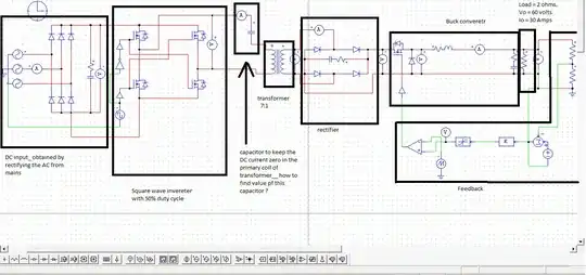
Just as a rough cut, I see that you have a 30A load and a 7:1 transformer, which suggests that the primary current is going to be a little over 4A. Assuming you want to pass that current with minimum loss, let's assume an AC impedance of about 1 Ω, which, at 50 kHz, implies a capacitance on the order of 3 µF. That's a lot of current (and voltage) for one capacitor, but as long as this is a theoretical/simulation exercise, it shouldn't matter.
There are some caveats, however. If the capacitor should happen to resonate with the primary of the transformer at the switching frequency, the current and voltage will rise dramatically, so check for this.
As a side note, I would point out that your drive circuit for the H-bridge isn't going to work in the real world. The high-side N-channel MOSFETs can't be driven with the same signals that are used for the low-side devices. Remember, the gate-to-source voltage on any MOSFET can't ever exceed a certain value, usually around ±20V.