6

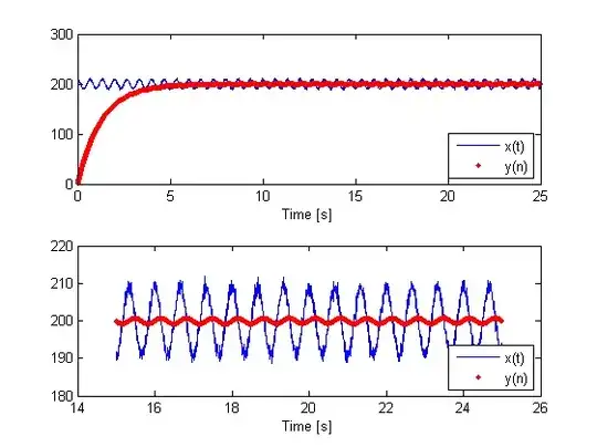
Im trying to implement a simple first order IIR filter on a MCU (PIC24FJ32GA002), without success until now. The filter is a DC tracking filter (low pass filter) whose purpose is to track DC component of a 1.5Hz signal. The difference equation was taken from a TI application note:

y(n)=Kx(n)+y(n-1)(1-K)
with K = 1/2^8

I made a MATLAB script to test it and it works well in the simulation. Code used:

K=1/2^8
b = K
a = [1 -(1-K)]

Fs=200; // sampling frequency
Ts=1/Fs;
Nx=5000; // number of samples
nT=Ts*(0:Nx-1);
fin=1.5; // signal frequency

randn('state',sum(100*clock));
noise=randn(1,Nx);
noise=noise-mean(noise);

xin=200+9*(cos(2*pi*fin*nT));
xin=xin+noise;

out = filter(b,a,xin);

Simulation Frequence response

However I can't implement it on a PIC24F microcontroller. i'm representing the coefficients in Q15 (1.15) format, storing them in short variables and using a long one for multiplications. Here it is the code:

short xn;
short y;
short b0 = 128, a1 = 32640; // Q15
long aux1, aux2;

// (...)

while(1){

    xn = readADC(adc_ch);

    aux1 = ((long)b0*xn) << 1;
    aux2 = ((long)a1*y) << 1;
    y = ((aux1 + aux2) >> 16);

    delay_ms(5);
}

Long cast is used to extend the signal so the multiplying operation is done correctly. After each multiplication I shift left one bit to remove the extended signal bit. When summing I shift right 16 bits to get y in Q15 format.

Im debugging the MCU with Pickit2 and "View->Watch" window (MPLAB IDE 8.53) and testing the filter with a DC signal (I change the DC signal with a potenciometer to test different values). The ADC has 10bit resolution and the MCU is supplied with 3.3V. Some results:

1V --> xn = 312 (correct), yn = 226 (incorrect)
1.5V --> xn = 470 (correct), yn = 228 (completely wrong)

What am I doing wrong? Any suggestions on how to implement this IIR filter on a 16bit MCU?

Many thanks in advance :)

Trygve Laugstøl
  • 1,410
  • 2
  • 19
  • 28
rasgo
  • 999
  • 2
  • 12
  • 20

6 Answers6

7

I didn't dive super far into your filter design, but just looking at the source code brings a couple of things up. For example, these lines:

aux1 = ((long)b0*xn) << 1;
aux2 = ((long)a1*y) << 1;
y = ((aux1 + aux2) >> 16);

The first issue I see is the ((long)b0*xn). I have ran across compilers that would compile this incorrectly as ((long)(b0*xn)), which is entirely wrong. Just to be on the safe side, I would write this as (((long)b0)*((long)xn)). To be sure, this is paranoid programming, but...

Next, when you do the "<<1", this is NOT the same as "*2". For most things, it's close, but not for DSP. It has to do with how the MCU/DSP handles overflow conditions and sign extensions, etc. But even if it did work as a *2, you are removing one bit of resolution that you don't need to remove. If you really have to do a *2, then do a *2 and let the compiler figure out if it could substitute a <<1 instead.

The >>16 is also problematic. Off the top of my head, I don't know if it's going to do a logical or arithmetic shift. You want an arithmetic shift. Arithmetic shifts will handle the sign bit correctly where a logical shift will insert zeros for the new bits. Besides, you can save bits of resolution by getting rid of the <<1 and changing the >>16 to >>15. Well, and changing all of these to normal multiplies and divides.

So here's the code I would use:

aux1 = ((long)b0) * ((long)xn);
aux2 = ((long)a1) * ((long)y);
y = (short)((aux1+aux2) / 32768);

Now, I don't claim that this will solve your problem. It may or may not, but it does improve your code.

  • 1
    It didn't solve but it helped on better understanding the code and the compiler "tricks". The problem was with the coefficients. It should be a1*xn and b0*y. A really lame mistake indeed eheh Thanks for your help! – rasgo Apr 12 '11 at 22:08
  • 1
    +1: technically the C standard doesn't define whether >> is an arithmetic or logical shift... or at least that's what the folks at Microchip told me a few years ago when I reported having problems using >> for power-of-2-divides because of lack of sign extensions. – Jason S Apr 20 '12 at 21:05
6

I suggest you replace "short" with "int16_t" and "long" with "int32_t". Save "short", "int", "long" etc. for places where the size doesn't really matter, such as loop indexes.

Then the algorithm will work the same if you compile on your desktop computer. It will be a lot easier to debug on the desktop. When it is working satisfactorily on the desktop, then move it to the microprocessor. To make this easier, factor the tricky routine into its own file. You will probably want to write a simple main() function for the desktop that exercises the routine and exits zero (for success) or nonzero (for fail).

Then integrate building and running the test into the build system for your project. Any development system worth considering will let you do this, but you might have to read the manual. I like GNU Make.

markrages
  • 19,905
  • 7
  • 59
  • 96
  • Even better, you don't have to define these typedefs yourself if your system has a : http://pubs.opengroup.org/onlinepubs/007904975/basedefs/stdint.h.html – Jason S Apr 20 '12 at 21:03
3

David Kessner mentioned the >> 16 as not being reliable, which is true. I've been bitten by that before, so now I always have a static assert in my code which checks that >> operates as I expect it.

He suggested an actual divide instead. But here's how to do a proper arithmetic >> 16 if it turns out that yours isn't.

union
{
     int16_t i16s[2];
    uint16_t i16u[2];

     int32_t i32s;
    uint32_t i32u;
}union32;

union32 x;
x.i32s = -809041920;

// now to divide by 65536

x.i16u[0] = x.i16u[1];        // The shift happens in one go.

                              // Now we do the sign extension
if (x.i16u[0] & 0x8000)       // Was this a negative number?
    x.i16u[1] = 0xFFFF;       // Then make sure the final result is still negative
else
    x.i16u[1] = 0x0000;       // Otherwise make sure the final result is still positive

// Now x.i32s = -12345

Check that your compiler is generating nice code for (x.i16u[0] & 0x8000). Microchip compilers don't always take advantage of the PIC's BTFSC instructions in cases like this. Especially the 8-bit compilers. Sometimes I'm forced to write this in asm when I really need the performance.

Doing the shift this way is much much faster on PICs which can only do shifts one bit at a time.

Rocketmagnet
  • 26,933
  • 17
  • 92
  • 177
  • +1 for using intNN_t and uintNN_t typedefs, also the union approach, both of which I use in my systems. – Jason S Apr 20 '12 at 21:01
  • 1
    @JasonS - Thanks. The union approach is what separates embedded developers from PC ones. The PC guys seem to have no idea how integers work. – Rocketmagnet Apr 20 '12 at 21:39
2

Using a dsPIC instead of the PIC24 might make things much easier (they are pin-compatible). The dsPIC compiler comes with a DSP library that includes IIR filters and the hardware supports fixed-point arithmetic directly.

Leon Heller
  • 38,774
  • 2
  • 60
  • 96
  • I must have to use this MCU (PIC24F) because it's to be used in a portable low power application and dsPIC doesn't meet that requirement. The filter is simple, it's a 1st order one. I suppose my problem is on converting double->fixed point format. However, reading the code I think I'm doing the right thing, but it doesn't work... I wonder why. – rasgo Apr 03 '11 at 16:43
  • 4
    "used in a portable low power application and dsPIC doesn't meet that requirement" <-- this kind of blanket statement sets off alarm bells in my head. Power consumption is application-dependent, and hardware support often means lower overall power consumption. Any low power application will keep the processor asleep most of the time, so reducing "on" time is the path to lower power consumption... – markrages Apr 03 '11 at 19:28
  • is that fixed point or floating point? Floating would be a plus, but you don't need a DSP to implement a bi-quad filter. You much more need a filter design software to find the parameters. – Federico Russo Jun 15 '11 at 11:03
1

It looks like you aren't ever giving y a value before you use it. You use y in the computation for aux2, which is correct because it is the filtered previous sample, but you have no idea what it is going to start as in this situation.

I would suggest you take an ADC sample before you enter your while(1) loop. Assign that value to y, delay 5 ms, then enter your loop. This will allow your filter to act normally.

I would also recommend that you go ahead and change your shorts to be longer variables. Unless you are running low on space, you will have much simpler code if you aren't having to type cast in every loop.

Kellenjb
  • 17,509
  • 5
  • 51
  • 87
1

Many early MCUs don't even have a multiply instruction, much less a divide. The IIR filter with the magic value with K = 1/2^8 was specifically designed for such MCUs.

// filter implements
// y(n)=K*x(n)+y(n-1)*(1-K)
// with K = 1/2^8.
// based on ideas from
// http://techref.massmind.org/techref/microchip/math/filter.htm
// WARNING: untested code.
// Uses no multiplies or divides.
// Eventually y converges to a kind of "average" of the x values.
short average; // global variable
// (...)
while(1){
    short xn = readADC(adc_ch);
    // hope that we don't overflow the subtract --
    // -- perhaps use saturating arithmetic here?
    short aux1 = xn - average;
    short aux2 = aux1 / 256;
    // compiler should use an arithmetic shift,
    // or perhaps an unaligned byte read, not an actual divide
    average += aux2;
    delay_ms(5);
}
davidcary
  • 17,426
  • 11
  • 66
  • 115