Volume, or in this case, audio amplitude or sound pressure, is a dynamic/variable thing. In other words, it will vary based on location and position of microphone, frequency and duration of the source audio, etc.
A little something to think about: When you watch a documentary video with a narrator and background music, there is often an audio effect called ducking going on. The narrator speaks, and the amplitude of the music goes down. When the narrator stops, the music becomes gradually louder again. In the small quiet gaps between words, however, the music doesn't become loud, so how does it know when the narrator is done?
When you apply a ducking effect, you set a few parameters to avoid having the background music try to be loud during every possible quiet gap. One of these is a delay: "Wait 1500 ms after detecting x amplitude to return to normal music volume."
When you think about having a circuit detect sound pressure, you have to ask whether you are interested in an average or an instantaneous measurement. A sound pressure meter, like this one you can get from Radio Shack, has both of these modes. You might want to experiment to see what you need for your application. If you use an instantaneous measurement, or a max threshold, you might set off your detection circuit by clapping your hands, when in fact you'd prefer it only be triggered by more continuous loud noise.
Your circuit would need to take multiple readings from the microphone input (analog to digital conversion (ADC)) and determine whether they constitute a trigger event or not. For example, you might read the value ten times per second, and average them. You might take readings for a few seconds instead; it depends on how long you require the sound pressure to be present to trigger the circuit.
Once you have that part worked out, you can incorporate a transistor and/or relay to switch on/off something else. A common, simple circuit is the "clap switch" of which there is an example at Circuiteasy.com.
Once you've switched the relay on or off, you then might need to reverse it, so you'd need to continue monitoring the input from the microphone. Remember the ducking example earlier, and be mindful of a delay. Otherwise, you might wind up turning on/off the secondary circuit much faster than you intended.
It all depends on what audio source you are trying to measure, what device you are switching on/off, and other details you omitted from your question. But hopefully this helps get you on the right track.
Addendum:
Per your edit, you will definitely want to use a relay to control a mains voltage device. However, if this is your first circuit, I strongly advise against that as a first project.
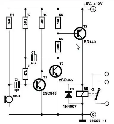
The first step will be to construct your sound detection circuit. You can probably find a schematic online for something that turns on LEDs (VU meter, for example) or look for sound-activated switch circuit (such as this example). They typically use a small electret microphone. Build your circuit on a breadboard and experiment with position of the microphone in relation to the sound. That may give you an idea of how sensitive it is (or not) and help get you started.
A microcontroller-based circuit will give you more flexibility, such as doing as I described above, taking multiple samples and evaluating them. If you're just starting with electronics, I don't recommend a microcontroller-based project as your first one. (But the Arduino platform is a great starting point for doing so.)
The circuit example I linked in the previous paragraph will be more basic, turning on the relay for a short time period set by C2.
For now, I would just use the relay to operate some other battery-powered device, so you can figure out how it works. When satisfied, check with someone more experienced to help you select and configure a relay to operate a mains-powered device or appliance.
See Also:
Here are some related questions on this site that you may find helpful: