15

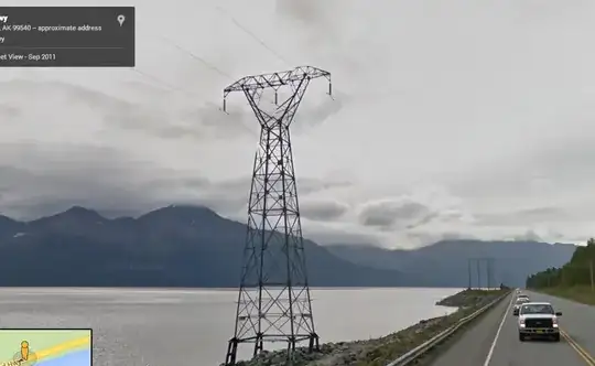
When I was in Alaska, I saw a high voltage line, but I didn't see the Neutral.

enter image description here

Is this because the water is conductive enough next to it to use as neutral? Or is it just two Phases.

enter image description here

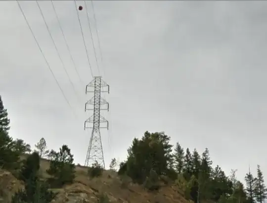
Where I live, Colorado, all of the power lines have the two neutral wires on top.

enter image description here

skyler
  • 10,136
  • 27
  • 80
  • 130
  • 1
    https://en.wikipedia.org/wiki/Zigzag_transformer "Its applications are for the creation of a missing neutral connection from an ungrounded 3-phase system" – jippie Aug 11 '14 at 18:42
  • 2
    Probably a duplicate: http://electronics.stackexchange.com/questions/93936/how-is-transition-from-three-phase-distribution-without-neutral-to-three-phase-c/94410#94410 – jippie Aug 11 '14 at 18:45
  • Also: http://en.wikipedia.org/wiki/Single_wire_earth_return – user49628 Aug 11 '14 at 18:50
  • ok, I edited it, where I live in colorado they have the extra neutral on top as seen in the photo above – skyler Aug 11 '14 at 20:08
  • 13
    As far as I know, the wires on top are not neutral, they are for distributing lightning strikes to multiple towers. – JYelton Aug 11 '14 at 20:17
  • @JYelton I agree, for as much as I know they are called "protection lines" or "guard lines" and they are *grounded*, as we can see because of the lack of insulators on the towers. – Vladimir Cravero Aug 11 '14 at 22:10
  • What I don't get of American power lines is their total lack of geometrical symmetry, I though inductance balancing was a thing, in EU I've always seen "spatial balanced" power lines... That's another question though. – Vladimir Cravero Aug 11 '14 at 22:12
  • @JYelton: Correct. These are ground wires. Part of their function is to shield against lightning strikes. The other part of their function is to carry the ground reference between towers, which helps to reduce each tower's impedance to ground. – Li-aung Yip Aug 12 '14 at 03:06
  • There're six wires on the last picture. Which are supposed to be neutral wires? – sharptooth Aug 13 '14 at 11:58
  • @sharptooth: No ground wires. That's double-circuit three phase (six active wires.) – Li-aung Yip Aug 13 '14 at 15:30
  • @Li-aungYip: That's what I though - such lines are quite common. – sharptooth Aug 14 '14 at 09:32

10 Answers10

13

This transmission is likely 3-phase in the Delta configuration, as opposed to the Wye (Y) configuration. Delta does not have a neutral line, whereas Wye does. Wikipedia link to balanced 3-phase circuits As you can see, the Wye connection has a neutral line, whereas the Delta does not.

Asa Graf
  • 321
  • 1
  • 8
  • That [wikipedia page](http://en.wikipedia.org/wiki/Three-phase_electric_power#Balanced_circuits) says the 4th neutral is *optional* on wye/star. – gbulmer Aug 12 '14 at 02:35
  • 1
    @gbulmer & acegard the neutral can be omitted if all phases (3 in this case) of a star topology network are used with equal load, since in that case the neutral has nothing to do anyways. In household and non-energy industry appliances this cannot be guaranteed, so the neutral is provided as well when a 3 phase connection is offered. In case of distribution networks and enegery-industry several steps are taken to ensure that the load is perfectly balanced, in this case that would happen at the transformator. – Mark Aug 12 '14 at 06:21
  • @Mark thank you, you are correct. So what you are saying is, in transmission lines such as this, the neutral is omitted because it is certain that the loads are balanced? – Asa Graf Aug 21 '14 at 03:43
  • @AsaGraf Almost: I'm saying that that is a configuration that allows for the neutral to be omitted under the circumstances listed. So it's either that or the grid in Delta-Formation which doesn't need a neutral in any case (see this answer http://electronics.stackexchange.com)/a/124845/35490 – Mark Aug 21 '14 at 04:53
11

Long distance AC transmission is normally 3-phase without neutral.

At the receiving end, a 3-phase transformer lowers the voltage from the "several kV range" to normal household levels (maybe a bit higher if it feeds an intermediate system). For households, a neutral is taken from the output side of the transformer but, on the long-distance transmission, the transformer primary (that receives the power) doesn't need a neutral.

Andy aka
  • 434,556
  • 28
  • 351
  • 777
11

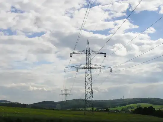
In my country, and probably in a lot of other countries, there is a ground wire at the top of each pylon. This ground wire is there for reasons of lightning protection. For the power transmission alone all you need is the three phases, because earth is used as reference potential. For long distance transmission there is also no strict need for a neutral wire. If there is nothing wrong, no current flows ever in the neutral line.

A pylon of type Donaumast

Dohn Joe
  • 319
  • 1
  • 9
9

Most long distance high voltage transmission is done in 3-phase Delta configuration, requiring only three cables.

This saves the cost of the fourth cable, used for the neutral line. It also avoids problems of imbalanced currents flowing through the fourth cable or the earth, since in Delta configuration any current imbalance on a phase is automatically shared on the other two phases, making for lower losses.

If 3-phase Wye configuration with four cables is used, it is generally only over short distances at the generating station and at the end-user's facility. Conversion at each end is generally achieved by Wye-Delta transformers.

In the bottom photo in this set the wires at the tops of the towers don't show up well, except one of them has a marker ball affixed to it to alert aviators. These top wires are connected to the tops of the towers without insulators and act to divert lighting strikes into the structure of the nearest towers, and then into the earth via ground rods, rather than striking the power cables and causing current and voltage surges in the grid.

Also, in the the bottom photo, the six cables comprise two independent 3-phase Delta transmission lines of three cables each.

ThreePhaseEel
  • 8,858
  • 4
  • 26
  • 41
Andrew P.
  • 226
  • 1
  • 4
7

High voltage power lines (the ones on huge towers with long insulators) are almost without exception 3-phase Delta alternating current, two independent groups if the tower has 6 wires. No neutral or ground needed. The two wires at the top of the tower in Colorado are not related to power distribution.

The only place the power company hangs neutral wires is low voltage circuits to homes and small businesses - these are typically the only consumers of non-3-phase power most people encounter.

paul
  • 2,083
  • 14
  • 7
6

3-Phase power transmission does not need a neutral wire. That is part of its attraction. It reduces the amount of material used to make the transmission lines by 1/4

The voltages are out of phase by 120 degrees, say A leads B by 120, B lead C by 120, C leads A by 120.

The maths of that are that A+B+C add up to 0, and hence do not need a 4th neutral wire.

When I was taught this stuff at school in the 70's, AFAICR the diagrams were all wye/star; maybe we were still excited by the UK's "National Grid" so this may have been taught to 16yo, but I likely covered it in Physics at 17-18yo. So our explanation may have been simplified :-)

wikipedia's three phase power 3 or 4 wire circuits show that neutral is optional in wye/star and unnecessary in delta. That 120 degree phase shift is the technique used, and wikipedia covers the theory in Balanced Circuits

You could demonstrate this if you have a spreadsheet which can draw three simultaneous line graphs, by creating three columns containing sin(x), sin(x+2pi/3), sin(x-2pi/3) (a few pi long), and plotting them.

This school of Physics shows the graphs of the maths which IMHO are clearer than wikipedias diagrams.

gbulmer
  • 10,040
  • 20
  • 29
  • yeah I learnt this in high school too, and it's hard to see a high-voltage line to use 4-wire Y layout – phuclv Aug 12 '14 at 11:37
3

Transmission lines don't serve a diversity of loads; they serve substations. They don't serve any single-phase loads at all.

Tesla's genius is that he figured out 120-degree three-phase power could be wired in a "delta" configuration without anything blowing up. This only requires 3 wires, as opposed to the 4 required by three-phase "wye" or or two-phase.

Large industrial loads (like substations) don't particularly need neutral for anything, so delta is used for economy of wire.

When you see a fourth or seventh wire on transmission lines, it is a lightning attractor to keep lightning off the conductors.

Delta power is great for high-power distribution; it is knocked down to either three-phase "wye" or split-phase near the customer. Industry has also been known to use 480 delta, though 480 wye/277 per leg is more versatile.

One advantage of 480 delta is that it can be supplied as an isolated system - sometimes important, say if it is going to be rectified to DC.

3
Where I live, Colorado, all of the power lines have the two neutral wires on top.

No, they don't. What your picture shows are two lightning arrestor wires at the top of the tower. Then there are two separate 3-phase groups on either side of the tower.

Olin Lathrop
  • 310,974
  • 36
  • 428
  • 915
1

Transmission line never connected in star or delta it's depend upon the source in which it is connected since all the generators are star connected in power system network bz of its advantages like less insulation (main advantage) and only one simple earth fault relay 90 percent of fault is detected.but generators is designed to be balance so it's all depends upon the load if load is balanced then there is no any problem because neutral current is zero so we don't use neutral wire. But in case of heavy unbalance like (unsymmetrical faults) the ground is used for the flow of zero sequence current because all the transformers and generators have their neutral grounded.thats why neutral wire is only require for satisfying single phase load (distribution purpose)only

-2

There is a Capacitance between the 3-phase power lines and the ground below the power lines.
If all lines are equal distance from the ground, each will produce the same Capicitance during the 3-phase cycle. On these towers you will not normally see a 4th wire. If the lines are placed on the tower vertically, so that each line is not equally distant from ground, then line/ground Capacitance will be different for each phase. This will felt back at the generator as an imbalance. That 4th wire is placed on top of the tower (sometimes 2 of them) is also at ground potential, so as to make Capacitance between the upper-most line and ground more equal to Capacitance between the lower lines and ground. Remember it is the potential, or voltage between conductors which creates Capacitance. It is current flowing in the conductors that causes Inductance. Ps. Check out OHMS law for alternating current. Capacitance Is continually changing with the voltage and it is one factor in the impedance of a circuit.

  • 4
    Welcome to EE.SE. (1) Capacitance is addressed by transposition. See https://electronics.stackexchange.com/questions/83152/how-do-transposition-towers-in-transmission-lines-work. (2) The fourth wire is lightning protection. (3) "*Remember it is the potential, or voltage between conductors which creates capacitance.*" No, capacitance exists whether there is voltage or not. I have a bunch of capacitors on my desk and they're all discharged. They still have capacitance. – Transistor Oct 28 '17 at 22:40
  • How do you know :D if you measure them, you apply voltage :D –  Oct 29 '17 at 03:56
  • 1
    @A.Marshall: Regarding your edit: "*Capacitance Is continually changing with the voltage and it is one factor in the impedance of a circuit.*" This is incorrect. The capacitance is defined and fixed by the geometry of the lines relative to each other and earth. It is not continually changing with voltage. \$ C \alpha \frac {A}{d} \$ where A is the area and d is the distance. Voltage doesn't come into the calculation. – Transistor Oct 29 '17 at 18:04