2

The question might sound kind of funny, but I'm unsure how else to word it. So...

Pictures!!

Currently, I have a setup like this:

schematic

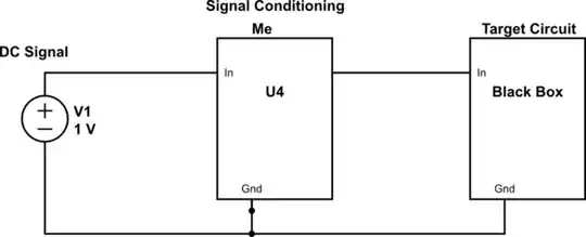
simulate this circuit – Schematic created using CircuitLab

What I would like to have is something like this:

schematic

simulate this circuit

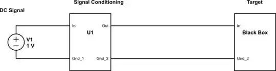
For the digital stuff, an optoisolator does the trick, and for AC signals an isolation transformer does the the trick and in each one of these devices, the input and output grounds are separated.

What method, or what should I be looking into in order to isolate two DC system grounds from each other? (The DC signal can vary from mV to 10's of volts.)

JYelton
  • 32,302
  • 33
  • 134
  • 249
efox29
  • 11,827
  • 9
  • 56
  • 102
  • A chopper configuration? Turn DC into AC, run it through an isolation transformer, then rectify and low-pass filter it. – jippie Aug 11 '14 at 06:04
  • What do you want to accomplish by isolating these grounds? – Phil Frost Aug 11 '14 at 10:46
  • @PhilFrost the current setup we have has some ground issues. Since we don't know whats inside this blackbox, we dont know internally how its grounds are connected. What we notice is that sometimes when we do "something" we get the incorrect behavior, but when we isolate the systems, we get the correct behaviour, which tells me that our two grounds are not friends. This was done with an AC signal, so I'm just looking to apply the same "fix" for all signals – efox29 Aug 11 '14 at 16:40
  • @efox29 What specifically are the "ground issues"? Noise? What kind (60 Hz hum?) Does the smoke get out? What are your minimum performance requirements? – Phil Frost Aug 11 '14 at 16:50
  • Well as an example, if I were to cut a ground connection, I would expect that particular signal to die or become erratic. That's not the case. The signal is still there and good. Becase all the signals we pass to it, share the same ground, the signal is finding an alternate path (which shouldnt happen). Does that kind of make sense ? – efox29 Aug 11 '14 at 18:27

4 Answers4

2

I can suggest two solutions. If the isolation can be less than perfect, meaning many megohms in the ground path, use an op-amp in differential mode for the DC signal input side and drive the black box with the ground and output of the difference amp.

For total isolation you can use optical much like the digital. The light (LED) brightness is controlled by an op-amp with an optical detector in the feedback. The same kind of detector is used on the isolated side and a simple calibration can correlate the two detectors. Check figure 3 here http://www.digikey.com/en/articles/techzone/2012/dec/linear-optical-isolation-for-safe-sensor-operation and these are the high end units http://www.ti.com/general/docs/lit/getliterature.tsp?literatureNumber=sbos129

Transformers are also still used of course. http://www.analog.com/static/importedfiles/tutorials/MT-071.pdf

C. Towne Springer
  • 2,141
  • 11
  • 14
1

There are "analog" optocouplers (e.g. the IL300 from Vishay) that can be used to opto couple analog signals with high linearity.

Instead of just one photodiodes they contain two. One is used for the isolated output and one for a feedback loop to ensure linear response:

enter image description here

Curd
  • 16,043
  • 34
  • 43
0

Analog Devices and Texas Instruments (and probably others) make isolation amplifiers specifically for this sort of application. TI ISO 122 and ISO 124 are a couple of choices.

Peter Bennett
  • 57,014
  • 1
  • 48
  • 127
0

The conventional method is convert your slow-moving DC signal to a frequency - this will still be the same frequency no-matter what isolation system you use and converting back to DC from a frequency is also relatively straight-forward i.e. there are chips that do this such as the VFC32

The question is how much accuracy do you need?

Andy aka
  • 434,556
  • 28
  • 351
  • 777