13

I'm looking to add a Peltier element to one of my projects. However, I want to sometimes heat and sometimes cool, depending on the ambient temperatures on both sides of the element.

Image from Wikimedia commons.

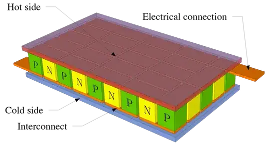
My first thought was to use a H-Bridge and then reverse the power for reversing the flow of heat. However, looking at the diagram above, it looks like it may be polarized. (I have no idea, though.)

Conclusion one: since you'd be flipping the power, the P-type would act like a N-type and vice versa. This doesn't seem logical, but I've never taken an electronics class, so it may very well be true. P and N probably are treated differently (chemically).

Conclusion two: it is polarized because the P-type always has to be attached to the positive side (and vice versa) so you can't flip it.

Is either one right? Can I use an H-Bridge for this?

JRE
  • 67,678
  • 8
  • 104
  • 179
Anonymous Penguin
  • 3,750
  • 8
  • 35
  • 57
  • 1
    That image from Wikipedia is wrong. There isn't a 'hot' or 'cold' side - it depends how you hook it up. You can easily see that if you mirror the element shown around it center, it's exactly the same element but with 'hot' and 'cold' flipped. – RJR Aug 06 '14 at 01:58

3 Answers3

13

A TEC is polarized in the sense that how it is connected matters. If you want to be able to heat and cool an element then a full Hbridge will work. This will allow you to pump current both directions across a TEC's terminals.

If you apply a positive voltage to a TEC in one polarization then side A will get warm and side B will cool. If you then reverse polarity then side A will cool and side B will get warm. So if you just need heat pumped in one direction then a half bridge or even direct connection will be fine.

Edit: Notice if you apply a positive voltage from one electrical connection to the other you are starting at "P". If you reverse connections you are still starting from "P" but now hot and cold will be flipped.

ACD
  • 2,338
  • 11
  • 26
  • 1
    I want the functionality both ways, so a full H bridge would be needed. – Anonymous Penguin Aug 06 '14 at 02:19
  • 2
    @ACD, Are there linear Hbridges? I've only run TEC's from a linear signal. I've heard that PWM is not so good for TEC's, because besides heat transfer they also have some internal heating. (which you'd like to be small.) The heat transfer is linear in the current but the internal heating goes as I^2. (So PWM generates more heat for a given heat transfer.) I've never really looked into it, have you run a TEC from an Hbridge? Maybe it's not that bad? – George Herold Aug 06 '14 at 02:20
  • 1
    @George Herold if this is an issue, you could filter the output of the H-bridge and you would get a continuous voltage from 0 to Vcc. With ripples probably. But this is better than a square signal if the TEC behaves as you said. – Blup1980 Aug 06 '14 at 05:32
  • This seems to be wrong. A Peltier element is basically a chain of diodes. Breakdown reverse voltage of a diode is usually several times higher than forward opening voltage. Amount of heat absorbed is $W=PIt$, with $P$ being Peltier coefficient, $I$ the current. If you just reverse the voltage, you'll most likely not have any noticeable current, and thus your TEC won't operate at all (you'll have $W\approx0$). Also see [this image](http://upload.wikimedia.org/wikipedia/commons/thumb/5/5b/Thermoelectric_Seebeck_power_module.jpg/1280px-Thermoelectric_Seebeck_power_module.jpg), notice "Hot Side". – Ruslan Aug 06 '14 at 08:24
  • 1
    @Ruslan this is simply not true. I have designed plenty of active regulation circuits for laser diodes that both cool or heat the diode by reversing current. Generally they say "hot side" so an orientation is known. They are telling you if you apply a positive voltage from Red to Black, that side will get hot. – ACD Aug 06 '14 at 12:29
  • 1
    @GeorgeHerold Blup is correct. You can make your PWM approximately DC with a large LC filter. (L in series, C parallel to terminals, C from each terminal to GND) – ACD Aug 06 '14 at 12:35
  • @ACD and I hope Blup is reading along too. OK so if the modulation frequency is high enough, the inductor gets smaller and it's not too bad. I've only done one laser diode TEC, and one to control the temperature of a permanent magnet. If you want low noise then linear is nice, but I guess if you keep the LC over there and my TEC over here... (do you use toroid and/or pot core inductors? I see too much pickup on open end inductors. – George Herold Aug 07 '14 at 01:33
  • 2
    Take a look ath the MAX1968/1969: these are commertial TEC controller chips. The reference schematics in the datasheet could be useful. Basically, the device is a full H bridge and PWM driver where you are supposed to add LC filters to form a pair of DC to DC converters. It also has current sense circuitry. The datasheet also has an example circuit for closed-loop temperature control with an analog PID controller. I built this circuit into an optical attenuator drive board and it works great. – alex.forencich Aug 11 '14 at 23:57
4

They are polarized, but the only "bad" thing about reversing the polarity is, the hot side gets cold and vice-versa. So you can use one side of a peltier as a heater or cooler by simply reversing the polarity. So if you were using it to cool a CPU, and have the polarity wrong, you will be heating the CPU side instead of cooling it.

2

Ok, it seems there are a lot of people here talking off the tops of their heads to be honest.

Ok maybe I'm a bit stern here, don't take offence LOL, it is an exchange of information after all.

The Peltier such as a TEC1-12706 for example, has one red wire and one black wire. The reason is that it is indeed polarity specific if one is to achieve the proper temperature profiles.

If one connects say for example the red to red and the black to black and runs 12VDC at say 5 amperes (well under the specifications of such a TC) then one will easily get a small drop of water to freeze in an instant with a suitably large heat sink on the opposite side (that is, the side which does not carry the label on the ceramic.) If one decides to reverse the current (connect the wires in the opposite direction and apply exactly the same voltage and current as above) using exactly the same heat sink, fan cooling etc etc. then one will not achieve temperatures below approximately 16-15C at best.

So, whilst the current can be switched it will not perform to specification unless connected as it was designed, hence the polarity of the cables.

If such cooling beyond 16C or so is not important as compared to switching the current then fair enough.

Don't believe me, simply perform this experiment yourself. I'm no electrical engineer, just a humble scientist who has done many many experiments with Peltier cells over the years.

JRE
  • 67,678
  • 8
  • 104
  • 179
  • 1
    This is absolute nonsense. I **did** try this test myself, only I started with running the module in reverse - red to black and black to red. As expected, it got quite cold and froze a drop of water AND pulled moisture out of the air and froze that too. Of course, if one were to run it the correct way after **without waiting for each side to return to ambient temperature first**, it would likely not repeat that performance. **Your methodology is flawed and your results do not demonstrate what you claim.** – metacollin Mar 18 '23 at 00:32