10

My circuit uses main electricity in parts of the circuit. However my AVR and other components only need 5V. So I'm using a step down transformer to generate 12V. It's then regulated to 5V.

The transformer won't convert it to dc for me will it?

It just steps it down then outputs a certain voltage depending on it's coils. So I would need to convert it to dc myself right?

Kortuk
  • 13,362
  • 8
  • 60
  • 85
Ageis
  • 3,311
  • 13
  • 44
  • 67
  • 6
    Yes, you answered your question correctly for yourself. – Jaroslav Cmunt Apr 01 '11 at 10:41
  • Bear in mind that transformers are rated for a.c. rms and fully loaded. Once you regulate and smooth, you get close to the peak voltage (minus diode drops), and will probably be 10% higher than that for small current loads on a small transformer (less for larger transformers, see the regulation figure). – Martin Apr 01 '11 at 10:47
  • Rectify it baby... http://en.wikipedia.org/wiki/Rectifier – kenny Apr 01 '11 at 10:52
  • Same exact application, somewhat different question: http://electronics.stackexchange.com/questions/515/how-to-convert-ac-to-dc – endolith Apr 01 '11 at 13:44
  • 1
    Comments below assume that you are talking about a [transformer](https://en.wikipedia.org/wiki/Transformer#/media/File:Transformer.filament.agr.jpg) when you say "transformer." Some people I know (not EEs) say "transformer" when they really mean "[external power supply](https://en.wikipedia.org/wiki/AC_adapter)." – Solomon Slow Aug 24 '17 at 15:10

4 Answers4

23

You are correct. The transformer will only reduce the voltage (and increase the available current), so you need to add additional circuitry to rectify, smooth and regulate your 12\$V_{AC}\$ transformer output to 5\$V_{DC}\$.

This is the type of circuit you should be looking to build:

AC to DC PSU

  1. The transformer reduces the voltage from mains to 12\$V_{AC}\$ (RMS).
  2. The Diode Bridge (known as a bridge rectifier) will convert 12\$V_{AC}\$ to 15\$V_{DC}\$. The voltage is \$\sqrt{2}\$ times minus two diode voltage drops higher than the input voltage because the rectifier output is the peak AC voltage, not the RMS AC voltage.
  3. The first capacitor will smooth out the ripples that come from the output of the AC to DC bridge rectifier.
  4. The LM7805 regulator will maintain a constant voltage as the load varies. For example if you are switching a light bulb on and off, the current will go up and down, and if you didn't have a regulator then the voltage would drop as the bulb is switched on. The regulator keeps it at the 5\$V_{DC}\$ your microcontroller needs.
  5. The final small capacitor filters out any noise or interference on the regulated side of the circuit.
stevenvh
  • 145,145
  • 21
  • 455
  • 667
BG100
  • 5,798
  • 4
  • 35
  • 48
  • Thanks for the schematic BG100. I see you seen Avatar. It was awesome. – Ageis Apr 01 '11 at 12:59
  • 1
    @BG100, sorry but this is a common error. 12V a.c. into a bridge does not product 12V d.c. More like 17V pk (12 * 1.414) – Martin Apr 01 '11 at 13:05
  • Sorry I've been forced onto this project. I'm on a steep learning curve here. So which one of these rectifiers will do the job for me. http://www.maplin.co.uk/bridge-rectifiers-19088 – Ageis Apr 01 '11 at 13:08
  • Also whats PIV and RMS – Ageis Apr 01 '11 at 13:09
  • @Martin: Absolutely right... I'll edit and correct. Thanks. – BG100 Apr 01 '11 at 13:27
  • @Ageis: They will probably all be suitable. As I don't know the details of what you're going to be powering with your supply, I would go for something in the middle. I suggest Maplins order code: AQ98G (the maplins web site is very poor for specs, so it's difficult to compare!) – BG100 Apr 01 '11 at 13:35
  • @Ageis: PIV = Peak Inverse Voltage - your rectifier needs to withstand at least 17v (see Martin's comment above). RMS = Root-Mean-Squared. This is the conventional way of measuring AC. A 12V rms voltage will produce the same power in a resistor as a 12V dc voltage. In stevenvh's answer, both waveforms have 12V rms voltage, but the first has an average over time of zero and the second (rectified) has an average of 10.8V. Both reach 17V at the positive peak. – MikeJ-UK Apr 01 '11 at 13:36
  • @Ageis: RMS means Root Mean Square. It's a bit tricky to understand this if you don't know a lot about AC waveforms. It's basically the average voltage of AC rather than the peak voltage. – BG100 Apr 01 '11 at 13:36
  • LOL I don't think I make it as a sparky then LOOOL. I'm training under city and guilds 2330 lv2. It's only a microcontroller and an lcd so I wouldn't think it will draw that much current. Do I only need one? In the schematic it looks like i need 4 – Ageis Apr 01 '11 at 13:47
  • @Ageis: Don't look too much into that... I just picked a mid range one from the list which will be more than adequate. You only need one. The 4 diodes are surrounded by a dotted box which represents your component. An alternative would be to buy 4 separate rectifier diodes and make your own bridge, but this is easier. – BG100 Apr 01 '11 at 13:53
10

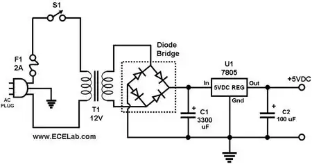
The transformer is the first part of the power supply, but you need more to get DC.

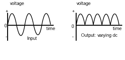
The varying input voltage of the transformer creates an equally varying magnetic field in the metal core. This magnetic field in turn creates an, again varying, voltage on the output. Both input and output voltage are sine waves. It's called AC (alternating current) because the sign of the output voltage changes continuously, 100 or 120 times per second, depending on the country you live in.
You rectify this AC voltage to get rid of the sign changes; one pin will always be positive with respect to the other one.

enter image description here

The one thing which remains to be done now is to flatten the curve, get rid of the bumps. This is done by a capacitor. You now have a DC (direct current) voltage which is already usable for a number of situations. This voltage, however, may still show slight variations, which may be unwanted. To get rid of those you follow the capacitor by a voltage regulator.

stevenvh
  • 145,145
  • 21
  • 455
  • 667
10

If you need 12 VDC, it may be simpler to use an off-the-shelf wall wart with a 12 VDC output. Such devices do convert to DC for you. A few of them use exactly the circuit BG100 shows, but nowadays many of them use a switching regulator technique that requires more parts, but has a lower net cost.

davidcary
  • 17,426
  • 11
  • 66
  • 115
  • +1 One should definitely know the principles behind a power supply, but when it comes to building a product (or hobby project) an off the shelf wall wart is the way to go: These things don't cost a fortune, and you get a nice case, cable, connector. Plus: You can be sure to meet all requirements for mains power (distances, isolation, ...) – 0x6d64 Sep 15 '11 at 09:51
  • 1
    .. and it makes product regulatory approval easier, and you don't have to worry about safety yourself. – pjc50 Sep 26 '12 at 11:09
5

The transformer won't convert it to dc for me will it?

Correct!

AFAIK it just steps it down then outputs a certain voltage depending on it's coils. So I would need to convert it to dc myself right?

Correct again!

Your transformer will convert \$120V_{AC}\$ to \$12V_{AC}\$. So you'll need to regulate it to \$5V_{DC}\$.

stevenvh
  • 145,145
  • 21
  • 455
  • 667
Daniel Grillo
  • 7,659
  • 18
  • 51
  • 69