4

This is a question about modifying an assembled board to make it easier to debug.

In a perfect world, I would have left the bottoms of these vias un-tented. Whoops.

I have two BGA parts on a PCB, with a 32 bit wide bus with a few control lines and a clock line connecting them. Almost all of these traces are only on internal layers. There looks like a signal integrity problem on the bus.

The good news is that the board only has parts on one side, and all the vias are through-all.

Can anyone suggest good ways to remove the tenting over the vias so they could be probed with an oscilloscope, or at least be able to solder 30 gauge wire to them?

The connection needs to be pretty good – the bus runs at about 100 MHz.

There are also some traces on the bottom layer, which I need to avoid damaging.

My current ideas:

  1. use x-acto knife to scrape off solder mask, first with a side to side scraping motion and then swivel the blade in a circular fashion.
  2. Use fine grit sand paper and remove the solder mask from the local area (covering several other vias, and maybe a few traces)

This article has a little more information too: http://www.edn.com/electronics-blogs/signal-integrity/4327009/Scrape-it-How-to-probe-a-microstrip-trace-with-no-accessible-test-points-or-vias

However I am hoping someone has a method that they consider a "joy to use."

I don’t want to just dive in; this prototype costs more than my car and I just have the one.

Marcus10110
  • 589
  • 3
  • 13
  • Joy to use? Not so sure about that, but I have successfully used the X-Acto knife method. Sometimes you can use the tip of a hot soldering iron to scrape the solder mask off too. – John D Aug 01 '14 at 22:53
  • A dremal with a small round burr tip. – Passerby Aug 01 '14 at 22:54
  • 1
    I think scraping is your best option, if that's a prototype (and costs like a car) maybe including some test points could have saved the day. If you have a steady hand that might work imho. – Vladimir Cravero Aug 01 '14 at 22:55
  • 2
    Design in proper test points in the first place... – Matt Young Aug 02 '14 at 19:07

3 Answers3

4

The accepted answer to this EE.SE question:

How to remove solder mask?

is to use a fibreglass brush pencil.

enter image description here

geometrikal
  • 4,921
  • 2
  • 23
  • 41
0

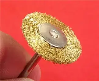
You might want to try a small brass wire brush (practice on a scrap board first). I think it would be best to get control of the brush by chucking it in a drill press (or mill if you have one) and use a heavy solid block of material (a cast iron angle bracket if you have one) and double-face tape the board to the angle bracket. There might not be enough room for that, and it might not work.

http://www.micromark.com/Brass-Brush-7and8-Inch-Dia,6632.html

When I've had to do this (thankfully only for one or two places at a time) I've always used a common #2 X-Acto blade, but I'm always worried the blade will snap since you're applying force sideways to get it to scrape- safety glasses are a must. Practice on a blank board of some other (cheap type) first, then practice on a blank copy of your real prototype as solder masks seem to vary a lot- this one might not be completely cured and you might be pleasantly surprised at how it comes off if it's 'hot off the press'.

Speaking of 'hot', it might be worth trying preheating the board moderately (say to 100°C) to soften it a bit, of course that will cure it more.

Spehro Pefhany
  • 376,485
  • 21
  • 320
  • 842
0

Certain more aggressive flux removers (e.g. TechSpray 1631-16S) will, with sufficient time and agitation, also remove solder mask. If very thin traces are involved, this might be safer than using a fiberglass or brass brush.

pericynthion
  • 6,164
  • 20
  • 34