9

I have a circuit which works on 21V DC and draws 3A maximum current. I need to get it tested to IEC 61000-4-4 and 61000-4-5 standards which are surge immunity tests.

I use a UL certified switch mode power supply to power my unit. The supply actually emits surges which is more than 21V (approximately +/-150V).

So I put in a TVS diode SMLJ22CABCT-ND in my circuit to protect against surges. This diode has a response time of about 5 picoseconds. But the pulses which are given in the surge tests are 8/20 μs pulses of 2KV. which in turn makes the power supply to give out surges as shown in the image. As you can see in the image, the output varies for a few microseconds. enter image description here DC output from the power supply after TVS diode

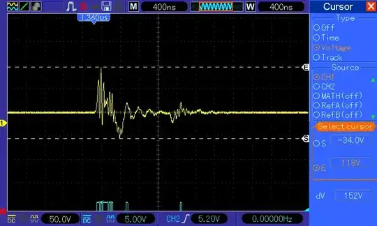
My question is why hasn't the TVS diode suppressed the high voltage. My circuit is damaged by this over voltage.

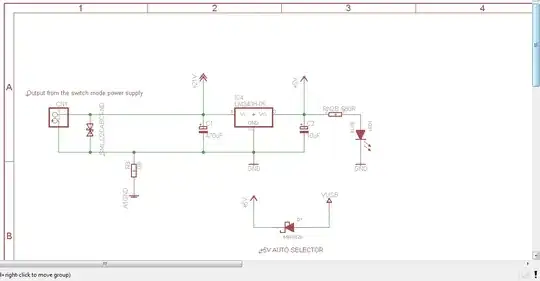
The schematic of the power circuit is given below.

There is not a lot of protection in the circuit. The 21V is taken for a different interface. I need to find a fix for this rather than designing a new circuit board.

Schematic

The testing circuit for the IEC 61000-4-5 is standard.

1KV across Live and Neutral; 2KV across Live and Earth, Neutral & Earth (detailed description)

mic
  • 323
  • 2
  • 7
  • 5
    Do you have a circuit of the test setup? – Spoon Aug 01 '14 at 12:46
  • Let's see your circuit, as Spoon says, but that doesn't sound like a very good power supply- or something else is going on. – Spehro Pefhany Aug 01 '14 at 12:54
  • Yea, we are going to need a circuit, or a schematic preferably – Funkyguy Aug 01 '14 at 13:43
  • Show us your complete power-conditioning circuit, including decoupling capacitors and any series inductors/beads. If all you have is the TVS, no wonder it isn't very effective. – Dave Tweed Aug 01 '14 at 13:55
  • I have edited my post. Please take a look at it – mic Aug 01 '14 at 15:34
  • Where and how are the measurements being made? .. I ask because inductive and or captive coupling from the test equipment could be giving you a false reading. – Spoon Aug 01 '14 at 20:52
  • There is no coupling from the test equipment. The firmware in my chip gets corrupted and the display goes crazy – mic Aug 02 '14 at 03:56
  • Can your device operate safely in a maximum voltage of 24.5 volts? – GR Tech Aug 02 '14 at 06:42
  • Yes even though it is not ideal, it still can. I have fitted a huge heat sink to the regulator. But when pulses are given the tvs does not cap the high voltage pulse which is above 150v and the regulator passes it on – mic Aug 02 '14 at 06:47
  • 2
    A tvs alone probably won't work. There needs to be either resistance or inductance or both to allow it to do its job properly. – Erik Friesen Aug 02 '14 at 19:09
  • If there's a lot of inductance due to poor layout in series with the TVS, then there's no way the TVS can clamp the voltage on the other side of the parasitic inductance. Can you measure right across the TVS device where the leads or pads enter the TVS package? If it's clamping there and not downstream then you know that you have too much inductance in series with the device. – John D Aug 02 '14 at 19:23
  • yes thanks @JohnD . I can do that. I will test it and post the result here. According to the datasheet, there is no mention of any parasitic inductance in the tvs diode. – mic Aug 03 '14 at 07:37
  • @JohnD. The TVS diode clamps the high frequency pulse when I measured right across it. But when I mount it on the board, it does not clamp the pulse. I guess there's some inductance on the PCB which prevents it from clamping it. I tried putting in an inductor(1500uH) in series before the TVS diode. Then it clamped the pulse. How do I calculate the exact inductance required in order to successfully clamp. Would a huge inductance cause any other issues to my system? – mic Aug 04 '14 at 11:12
  • @mic You shouldn't need a huge inductor, just something maybe >> than the value of the parasitic inductance, which is probably some number of nanohenries. I would think 1uH or less would be sufficient. Make sure the inductor isn't saturated with your DC current, and make sure there's a path for the current to flow if the input is disconnected. (Could be a diode across the inductor that's normally reverse-biased.) – John D Aug 04 '14 at 17:34
  • Have you considered a [MOV](https://en.wikipedia.org/wiki/Varistor) also, for higher-current clamping ability? Note that in a sustained over-voltage event, a MOV could catch fire, so a series slow-blow fuse is recommended on power input. Also tinker with a power choke and/or common-mode choke. Both will help to filter out any power noise and increase the reliability of the circuit. But if the power supply is producing these spikes, shouldn't you be looking at remedying this source of the problem, as opposed to dealing with the spikes yourself? A power supply shouldn't be producing spikes. – rdtsc Jun 22 '15 at 11:59
  • What was your final solution on this? Any results you can share? – Rev Mar 17 '17 at 13:17
  • Using trial & error method, the chosen inductor was 7.5uH. Also we used an ultra fast low drop schottky diode on the output of the regulator. – mic Mar 18 '17 at 10:41

2 Answers2

1

Very often the parasitic impedance between the lines and diode is some nanohenries. This caused by the length of diode leads.

enter image description here

This impedance slowing the response of TVS diode by nanoseconds, thus the transient pulse can pass.
You can use a TVS diode with so called “flow through design” in which you have to pass rail and ground through the same package.

enter image description here

Of course this needs a proper design of PCB.

GR Tech
  • 2,208
  • 2
  • 15
  • 17
  • This is the TVS diode which i'm using now. [link](http://www.digikey.com/product-detail/en/SMLJ22CA/SMLJ22CABCT-ND/2253676) I have soldered the TVS diode on to the pins directly. I am working with an existing PCB. I'm trying to apply a fix. Will adding a capacitor in parallel to the diode solve the issue here? .( counteract the inductance) – mic Aug 03 '14 at 05:18
  • I just read it in a similar [post](https://electronics.stackexchange.com/questions/23185/tvs-diode-layout) here. I've also found an article about overcoming the parasittic inductance issues [here](http://www.vishay.com/docs/88450/tvsplace.pdf). – mic Aug 03 '14 at 06:39
  • 1
    @mic may be not a capacitor but it will be interesting to add an inductor 100 ~ 470μH (at the rated current) after the diode, in series with power supply rail of your under protection device, just to slow the rise time of transient pulse and finaly to absorbed by shunt. I haven't test this suggestion – GR Tech Aug 03 '14 at 07:10
  • @ GR Tech should it be before or after? According to the doc, shouldn't it be before the diode? – mic Aug 03 '14 at 07:20
1

To bypass the transient, you need to use a capacitor of $$ 1.6 \mu f \text{ }(or\text{ }larger)$$ in parallel with the diode.

Guill
  • 2,430
  • 10
  • 6
  • There is a capacitor in the circuit already. the 470uf capacitor is in parallel with the tvs diode. Also is there any calculation involved in determining the value of the capacitor – mic Aug 11 '14 at 08:43
  • This isn't always a possibility. You cannot just chuck capacitance down to slew the transient, what about on a communication bus? silicon TVS's are fine as long as they are correctly sized, placed correctly with appropriate steering diodes (if needed) –  Jun 22 '15 at 11:40
  • @mic: Even though you already have a 470uf across the diode, for some reason they are not good at suppressing high frequency noise. Try a ceramic of around 2 uf, of the appropriate voltage. – Guill Apr 16 '17 at 03:11