3

I plan to use the HC-06 serial bluetooth module with an Arduino Leonardo. To my knowledge, the Arduino's serial pins output at 5V with 40mA of current. The HC-06's datasheet says it will accept input at 3V - 4.2V with 20mA - 40mA of current. I'm more of a programmer than an electrical engineer, but this tells me I will need a resistor between the Arduino's TX pin and the HC-06's RX pin. From my calculations I will need a resistor with 82.5 Ohms of resistance:

$$r = \frac{V}{I} = \frac{3.3V}{0.04A} = 82.5 \Omega$$

Is this the correct way to solve the problem? Online I've seen people solve the exact same issue using a voltage divider with a 10kOhm resistor leading from the Arduino's TX pin to the HC-06's RX pin and a 20kOhm resistor leading from the HC-06's RX pin to ground. So, what's the correct way to solve this problem? If a voltage divider is the solution, why and how does it work? Or why does simply putting in a 82.5 Ohm resistor not work?

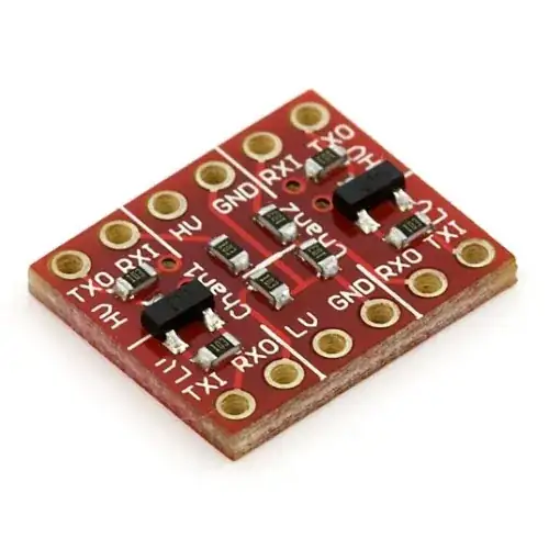
EDIT: For simplicity sake, let me reiterate my question from a more general perspective. The HC-06 module requires a power supply voltage of 3.3V (which can come from the Arduino's 3.3V pin) and will also only accept logic inputs at 3.3V. So, what is an easy way to achieve this voltage reduction for the serial wire?

Parker Hoyes
  • 173
  • 1
  • 6
  • 5
    With your 82.5 Ohm in series, that is based on the assumption that there will always and only be 40mA flowing. If the Bluetooth module, for any reason, draws less current, then the voltage dropped across that resistor will change (will decrease). This will cause the voltage seen by the Bluetooth module to increase, which could violate it's input limits. – Adam Head Jul 31 '14 at 16:20
  • 1
    Engineering-quality data sheets for this module seem hard to find, but it would appear that "20-40 ma" is the **power supply current**. The data inputs are likely CMOS, one source claims "CMOS with a weak pulldown" – Chris Stratton Jul 31 '14 at 20:02
  • @Cornelius I've edited the post to be more specific to the situation and more clear as to what I am trying to accomplish – Parker Hoyes Jul 31 '14 at 21:10
  • We understand what you are trying to do, its not your fault. Somebody just has a vendetta against any answers for this question. – Funkyguy Jul 31 '14 at 21:25
  • Nope, only against the posting of **wrong** answers. But now we have a correct one which shows actual understanding of the issues involved. – Chris Stratton Jul 31 '14 at 23:23

3 Answers3

2

There are two main sets of characteristics quoted for pins, absolute maximum ratings and typical ratings.

The HC-06's datasheet says it will accept input at 3V - 4.2V with 20mA - 40mA

Those are absolute ratings. The pin is rated to handle 3V to 4.2V and 20mA - 40mA current. In a normal circuit, digital input pins will draw very little current, as they are CMOS logic gates. There might be a pull-up resistor, that connects the pin internally to Vcc, or a pull-down resistor, that connects the pin internally to GND, which will increase the current draw.

Without the pull-up or pull-down resistor enabled, the pin has very high input impedance. Your proposed one resistor circuit looks like this:

schematic

simulate this circuit – Schematic created using CircuitLab

You effectively have a voltage divider with the other resistance being the input impedance of the HC-06 input pin.

So the voltage on the RX pin with 5V on the Arduino TX pin would be:

$$ V_{RX} = 5V \frac{R_{really\,really\,big}}{R_{line} + R_{really\,really\,big}} \approx 5V$$

This is outside the maximum voltage rating.

Solution

The solution is to use some kind of level shifter. The resistors in the divider should be high enough not to violate the Arduino maximum current output and much less than the input impedance of the input pin. They also must be low enough that the input capacitance of the pin doesn't 'smear' the signal too much (slew rate). You can think of the capacitance as resisting the change in voltage, so sharp inputs start to get rounded off: (image taken from http://www.johnloomis.org)

enter image description here

For you quoted figures we would then have:

$$ V_{RX} = 5V \frac{\left(\frac{1}{20K} + \frac{1}{ R_{really\,really\,big}}\right)^{-1}}{10K + \left(\frac{1}{20K} + \frac{1}{ R_{really\,really\,big}}\right)^{-1}} \approx 5V \frac{20K}{10K + 20K} \approx 3.3V$$

In Arduino land, people would by a logic level shifter board for this purpose. One common one has a voltage divider for 5V TX to 3.3V RX, and a transistor for 3.3V TX to 5V RX. Others have transistors both ways, so that the voltages can be different from 5V and 3.3V as using a voltage divider the ratio is fixed, and to effectively have a very low output impedance on the TX pins and thus avoid slew rate problems.

enter image description here

geometrikal
  • 4,921
  • 2
  • 23
  • 41
1

While a resistor divider will push the voltage down to proper levels, it is inefficient for serial communications or any quickly changing signal. Resistors not only change the relationship between voltage and current, they also add a longer slew rate to the changing signal, meaning it will actually take longer for the signal to rise up to its HIGH logic level. This will pose a problem with UART.

A better solution is to use a logic level converter, particularly one that is made to handle communication protocols. You will give this device a 3.3V and a 5V as well as the signals as indicated by the documentation. The Leonardo has a 3.3V pin I believe so you should be fine.

Good luck!

Funkyguy
  • 3,558
  • 1
  • 21
  • 45
  • **NO** This is mistaken as it only perpetuates the original poster's misunderstanding of the difference between a current rating and the current actual flowing in typical usage. One does not use a single resistor, but rather a resistive divider. For real-world input impedances, short wiring, and serial baud rates that it would make sense to use when proxying over bluetooth, it tends to work quite well. – Chris Stratton Jul 31 '14 at 17:28
  • @ChrisStratton The question isn't about absolute maximum ratings and operational characteristics. Its about making the thing work in a correct manner. I did add clarification for the first statement that he would need a resistor divider although apart from that, I don't see how anything you said disproves the answer I've given to the question. – Funkyguy Jul 31 '14 at 17:31
  • "While a resistor divider will push the voltage down to proper levels at 40mA, this could be a problem if the HC-06 pulls anything less than 40mA" **GROSSLY MISTAKEN**. You really need to stop posting quick, wrong answers. – Chris Stratton Jul 31 '14 at 17:51
  • @ChrisStratton Alright fixed. Boom, right – Funkyguy Jul 31 '14 at 17:58
  • Let it be known that the actual answer to the question has always been right. Chris is just correcting the errors in the related material that I'd written regarding resistors. – Funkyguy Jul 31 '14 at 18:08
  • No, the answer is, and remains **wrong** in its conclusions re resistive dividers. Resistive dividers are commonly used for level conversion in settings such as this. One may need to apply them with care, but it is frequently and properly done. – Chris Stratton Jul 31 '14 at 18:10
  • 2
    @ChrisStratton I am starting to think you incapable of posting anything that doesn't use bold text. Either way, resistor dividers introduce a slew rate that can be problematic as speeds increase. Regardless I'm done with this. If you want to make sure the answer is right by nitpicking at everything, the answer it yourself instead of badgering another answer that presents a good and proper solution. – Funkyguy Jul 31 '14 at 18:16
0

The simplest solution is a resistive divider to lower voltage from 5V to 3.3 V, but you can't raise 3.3 V to 5V without a transistor. Probably, there will be no problem, because Arduino will sense the 3.3 V input as HIGH input, and you can get a working circuit with only resistive divider on the Arduino TX - HC-06 RX line.

The best solution would be a level shifter. You can build transistor level shifters like https://electronics.stackexchange.com/a/107388/40609. Or simpler, use the 74LVC245 IC.

If a voltage divider is the solution, why and how does it work? Or why does simply putting in a 82.5 Ohm resistor not work?

You should read Voltage Divider vs. Resistor in Series

Cornelius
  • 5,048
  • 4
  • 26
  • 45